I can’t thank you enough.
It’s working properly.
Now i will keep going in this unwraping stuff so i can map it out!
I can’t thank you enough.
It’s working properly.
Now i will keep going in this unwraping stuff so i can map it out!
@Louis
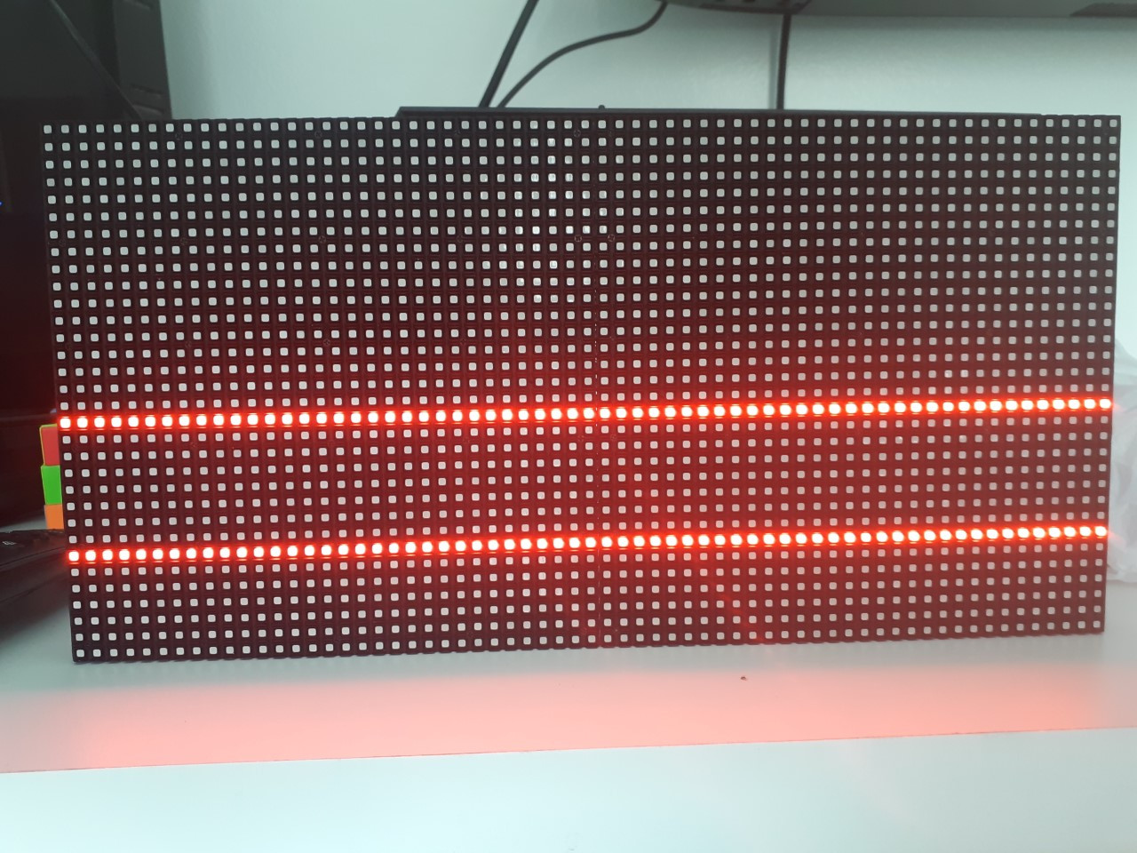
After testing the map i made it’s like this, even when i try sketches i saved and that i know is working.
What do you think, hardware damage? libraries mess?
I tried running Blink and its ok but i think maybe some digital port may be damaged.
Help pls 
It’s not working even if you remove all the library changes you made and run a sketch using an existing panel map?
Exactly.
I removed the library and put a new one and it’s still displaying those two lines only, If I remove from USB and connect on a power supply it starts blinking like crazy.
Sorry, it’s hard to diagnose what’s going on. It doesn’t look to me like the panel is being refreshed, it’s just stuck with some LEDs on with a single address. If you had spare ESP32s or panels I imagine you would have tried them already, that’s what I would try.
@matbks try this
const PanelMappingEntry panelMapP5_2727_64x32 = _ {
{0,64,64},
{8,0,64},
{0,0,0}
}
from the following link:
Thank you!
But that’s exactly what i did
i am very confident that some digital port was damaged by the code, i will use another esp32 and if it work again ill see if i missed any row by running the mapping code again.
I made all the tutorial, very calm, i’m pretty sure i made all right 
Yeah, i was right, the esp32 got damaged when i run the map test somehow.
I put another in place and now the reverse engeneering is working again.
Please, analyse the files below and tell me whats wrong, i commented it just for be easy for u to analyse, the original one is not commented.
@matbks
Hello Mateus, I used your files on a teensy 3.2 and teensy 4.0, both work for me, I don’t have an ESP32 to test.
Problem is when you use in ur code the panel type I made. As map testing.
I don’t see anything wrong with the mapping you added. I’ve never had an ESP32 board damaged while trying unstable code on it. It seems unlikely that the code broke it. It’s possible to damage a pin by driving a pin connected to GND on the panel with 3.3V (e.g. the D and E address lines which aren’t used by the panel and are probably grounded, but I’ve never seen this happen and I’ve driven panels with the wrong config). I think it’s a coincidence that you tried some code and the ESP32 broke, but I could be wrong. Does the ESP32 program and run code? If it’s just one or two pins that are damaged, you could swap the pins used in the MatrixHardware config file and use pins that are working.
I used another esp32 and it worked just fine when I run the reverse eng. Sketch. Then I played again the map testing sketch and the new esp32 entered in the same mode that before, two fixed red lines and can’t compile unless holding boot. but this time I did not switched to power supply for testing (probably the step that damaged a port before.)
Did I forget of editing some anothler file?
two red lines and can’t compile unless holding boot
I think that’s more or less normal with the FORUM_PINOUT, as some of the lines that drive the panel are also used to select the boot mode during reset. You might have better luck with a different pinout. I’m used to holding the boot button or sometimes holding boot and pressing reset before programming with the ESP32 depending on the circuit I’m using.
I’m not sure if this is the complete list of pins that ideally should be left floating during reset, but it’s at least most of them (copied from another project):
// IO12 (MTDI), IO15 (MTDO), GPIO0 • GPIO2 • GPIO5 are used for boot strapping, so shouldn't be driven during boot
entered in the same mode that before, two fixed red lines
I don’t know why you’re seeing this. I just added your config to my local SmartMatrix Library, and tried it and I’m seeing a partial image, not just two red lines. I’m using a circuit with a latch, not bare wires though
What am I supposed to see during map test?
Isnt it the red dot going from pixel to pixel In a linear way? Or is it a image? Cause I used to see those red rows when trying to run in usb a sketch that demands more power than USB can give, but if it’s just a red pixel moving it should be just fine in USB as well as reverse engeneering sketch runs.
I ask cause I don’t want to burn another esp32 ports (if that’s what rly happened)
Yes, just one dot at a time
Your update worked @Louis
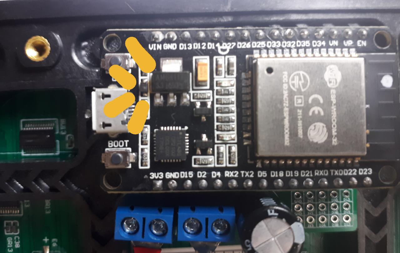
But looks like the ESP32 can’t handle that much current.
The component showed below starts smoking as the demo sketch runs.
Any idea of how i can handle this ?
How are you powering the panel? You shouldn’t be powering from USB. That part looks like a diode which is meant to prevent external power from flowing to the computer. You likely can still run your ESP32 from external power if your shield supports it. You should contact the person that designed your hardware for support
I am powering it from external power supply connected to the esp32’s micro usb.
I will contact the designer of the shield.
Louis, thank you so much!
I didn’t test it time enough but i lowered the brightness to 15% and so far so good!
For anyone coming across this post in the future the following are the ESP32 “strapping pins”
These are used to put the ESP32 into bootloader or flashing mode.
Source: ESP32 Pinout Reference: Which GPIO pins should you use? | Random Nerd Tutorials
Typically from my (relatively limited) experience with the ESP32 this is not much of a problem with most devices but seams to be particularly sensitive to RGB matrices for obvious reasons as these pins are being constantly switch in rapid succession in order to drive the panel.