// This is how many color levels the display shows - the more the slower the update
//#define PxMATRIX_COLOR_DEPTH 4
// Defines the speed of the SPI bus (reducing this may help if you experience noisy images)
//#define PxMATRIX_SPI_FREQUENCY 20000000
// Creates a second buffer for backround drawing (doubles the required RAM)
#define PxMATRIX_double_buffer true
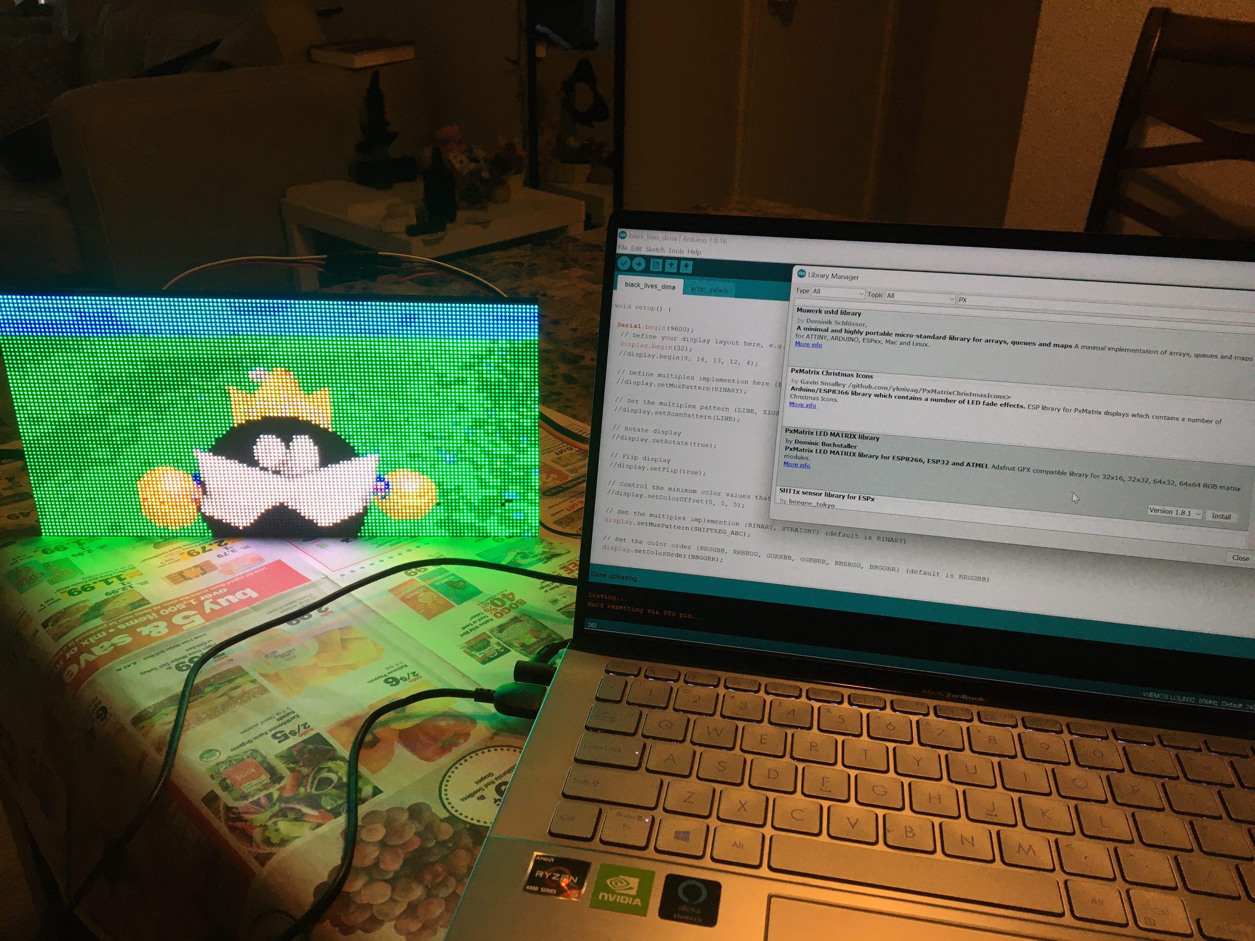
#include <PxMatrix.h>
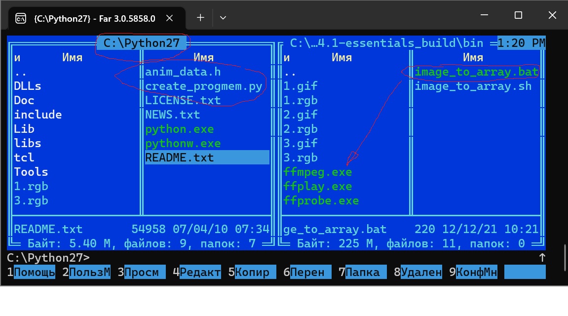
#include “anim_data.h”
// Pins for LED MATRIX
#ifdef ESP32
#define P_LAT 22
#define P_A 19
#define P_B 23
#define P_C 18
#define P_D 5
#define P_E 15
#define P_OE 16
hw_timer_t * timer = NULL;
portMUX_TYPE timerMux = portMUX_INITIALIZER_UNLOCKED;
#endif
#ifdef ESP8266
#include <Ticker.h>
Ticker display_ticker;
#define P_LAT 16
#define P_A 5
#define P_B 4
#define P_C 15
#define P_D 12
#define P_E 0
#define P_OE 2
#endif
#define matrix_width 128
#define matrix_height 64
#define RGB 565
#if RGB==565
#define frame_size matrix_widthmatrix_height2
#else
#define frame_size matrix_widthmatrix_height3
#endif
uint16_t frame_no=0;
unsigned long anim_offset=0;
union single_double{
uint8_t two[2];
uint16_t one;
} this_single_double;
// This defines the ‘on’ time of the display is us. The larger this number,
// the brighter the display. If too large the ESP will crash
uint8_t display_draw_time=10; //30-70 is usually fine
PxMATRIX display(128,64,P_LAT, P_OE,P_A,P_B,P_C);
//PxMATRIX display(64,32,P_LAT, P_OE,P_A,P_B,P_C,P_D);
//PxMATRIX display(64,64,P_LAT, P_OE,P_A,P_B,P_C,P_D,P_E);
// Some standard colors
uint16_t myRED = display.color565(255, 0, 0);
uint16_t myGREEN = display.color565(0, 255, 0);
uint16_t myBLUE = display.color565(0, 0, 255);
uint16_t myWHITE = display.color565(255, 255, 255);
uint16_t myYELLOW = display.color565(255, 255, 0);
uint16_t myCYAN = display.color565(0, 255, 255);
uint16_t myMAGENTA = display.color565(255, 0, 255);
uint16_t myBLACK = display.color565(0, 0, 0);
uint16_t myCOLORS[8]={myRED,myGREEN,myBLUE,myWHITE,myYELLOW,myCYAN,myMAGENTA,myBLACK};
#ifdef ESP8266
// ISR for display refresh
void display_updater()
{
display.display(display_draw_time);
}
#endif
#ifdef ESP32
void IRAM_ATTR display_updater(){
// Increment the counter and set the time of ISR
portENTER_CRITICAL_ISR(&timerMux);
display.display(display_draw_time);
portEXIT_CRITICAL_ISR(&timerMux);
}
#endif
void display_update_enable(bool is_enable)
{
#ifdef ESP8266
if (is_enable)
display_ticker.attach(0.001, display_updater);
else
display_ticker.detach();
#endif
#ifdef ESP32
if (is_enable)
{
timer = timerBegin(0, 80, true);
timerAttachInterrupt(timer, &display_updater, true);
timerAlarmWrite(timer, 2000, true);
timerAlarmEnable(timer);
}
else
{
timerDetachInterrupt(timer);
timerAlarmDisable(timer);
}
#endif
}
unsigned long getAnimOffset(uint8_t anim_no)
{
unsigned long offset=0;
for (uint8_t count=0;count<anim_no;count++)
{
offset=offset+animation_lengths[count]*frame_size;
}
//Serial.println("anim_no: " + String(anim_no) + ", length: " + String(animation_lengths[anim_no])+ ", offset: " + String(offset));
return offset;
}
uint8_t line_buffer[matrix_width*2];
// This draws the pixel animation to the frame buffer in animation view
void draw_image ()
{
unsigned long frame_offset=anim_offset+frame_no*frame_size;
for (int yy=0;yy<matrix_height;yy++){
memcpy_P(line_buffer, animations+frame_offset+yymatrix_width2, matrix_width*2);
for (int xx=0;xx<matrix_width;xx++){
  this_single_double.two[0]=line_buffer[xx*2];
  this_single_double.two[1]=line_buffer[xx*2+1];


  display.drawPixelRGB565(xx,yy, this_single_double.one);


}
yield();
}
}
void setup() {
Serial.begin(9600);
// Define your display layout here, e.g. 1/8 step, and optional SPI pins begin(row_pattern, CLK, MOSI, MISO, SS)
display.begin(32);
//display.begin(8, 14, 13, 12, 4);
// Define multiplex implemention here {BINARY, STRAIGHT} (default is BINARY)
//display.setMuxPattern(BINARY);
// Set the multiplex pattern {LINE, ZIGZAG,ZZAGG, ZAGGIZ, WZAGZIG, VZAG, ZAGZIG} (default is LINE)
//display.setScanPattern(LINE);
// Rotate display
//display.setRotate(true);
// Flip display
//display.setFlip(true);
// Control the minimum color values that result in an active pixel
//display.setColorOffset(5, 5, 5);
// Set the multiplex implemention {BINARY, STRAIGHT} (default is BINARY)
display.setMuxPattern(SHIFTREG_ABC);
// Set the color order {RRGGBB, RRBBGG, GGRRBB, GGBBRR, BBRRGG, BBGGRR} (default is RRGGBB)
display.setColorOrder(BBGGRR);
// Set the time in microseconds that we pause after selecting each mux channel
// (May help if some rows are missing / the mux chip is too slow)
//display.setMuxDelay(0,1,0,0,0);
// Set the number of panels that make up the display area width (default is 1)
//display.setPanelsWidth(2);
// Set the brightness of the panels (default is 255)
//display.setBrightness(50);
// Set driver chip type
display.setDriverChip(FM6124);
display.clearDisplay();
display.setTextColor(myCYAN);
display.setCursor(2,0);
display.print(“Pixel”);
display.setTextColor(myMAGENTA);
display.setCursor(2,8);
display.print(“Time”);
display_update_enable(true);
display.showBuffer();
delay(1000);
Serial.println("Initi complete");
}
void loop() {
for (uint8_t anim_index=0; anim_index<sizeof(animation_lengths)-1;anim_index++)
{
// Display image or animation
anim_offset=getAnimOffset(anim_index);
frame_no=0;
unsigned long start_time=millis();
while ((millis()-start_time)<8000)
{
  draw_image();
  display.showBuffer();
  //Serial.println(anim_offset);

  frame_no++;
  if (frame_no>=animation_lengths[anim_index])
    frame_no=0;
  delay(100);

}
/**
// Display static
start_time=millis();
anim_offset=getAnimOffset(5);
frame_no=0;
while ((millis()-start_time)<1000)
{
  draw_image();
  display.showBuffer();
  frame_no++;
  if (frame_no>=animation_lengths[5])
    frame_no=0;
  delay(50);
}
**/
}
}