@pinballsp is correct, the ADDX pins all have to be in the same port. When you changed to the Teensy 3.6, did you use pin 37, or stick with pin 16?
SmartLED Shield V4 has a solution to the shortage of pins, actually not requiring any dedicated pins for ADDX, and using an external flip flop to store the ADDX signals instead. It’s out of stock right now but you can check the hardware design files in github and wire up the circuit yourself. 1/32 using the V4 circuit isn’t there yet, with @pinballsp’s help I hope to get this in the next release.
@pinballsp Ah hah, the PORTC makes sense, I’ll try going back to Teensy 3.2 and try pin 15 instead. I’ll also try the refresh rate, thanks!
@Louis Correct, I adjusted to pin 37 when using Teensy 3.6. Great, I assume the 74245 & 74374 are the only necessary components needed for that. I’ll order those and give it a shot.
Besides the ADDX signals on the 74374, there are 9 signals that need to be buffered, so you’ll need two 74245s, or one 74245 and one single gate buffer.
So I’ve tried setRefreshRate(120) and still getting some flickering, but I think that may just be due to the jumper wires. I’ll try milling a board with short traces and see how that works.
However, when using Teensy 3.2, half the screen doesn’t work (two separate quarters), even though I’m using pin 15 now (PORTC). Switching to Teensy 3.6 and port 37, it does work properly. (I am changing ADDX_TEENSY_PIN_4 when testing between them).
I hooked up the supposedly 1/32 scan panel I have and started adding @pinballsp’s changes to the code, but quickly found that my panel is actually 1/16 scan. I placed an order for this panel on Aliexpress and hope to have it within the next month so I can make these changes and test.
Have there been any updates on the new version of the library that would support 1/32 panels on the V4 shield? I plan to use a set of panels like @pinballsp, but I’m using your latest shield and I’m not sure if his code changes are compatible with the external flipflops (or did you use a counter?) that the V4 shield uses to drive the address pins on the panels. I just thought I’d ask before I start trying to implement 1/32 changes myself.
I just pushed changes to support 64-row /32 panels to GitHub. It’s not packaged up into a release yet, but you can download the code. I tested it on the 64x64/32 panel I received yesterday.
@samy commented on poor refresh rate when driving with the Teensy 3.2: that’s to be expected, it’s a lot of work for the Teensy 3.2 to refresh a 64x64 panel, and it’s even more work when it’s /32 scan and not two 64x32/16 panels strung together. The Teensy 3.5/3.6 should do better.
I didn’t add @pinballsp’s changes to support V1-V3 shields as there are more changes needed. I don’t want to break support for any existing users by driving a new pin unexpectedly. I don’t have the time to wire up a 5th pin on my Teensy, so I wouldn’t be able to test the changes myself. If someone really wants /32 panel support added to the library, and you can’t make the changes yourself following @pinballsp’s code above, please ask. There are other SmartMatrix Library features I feel are more important, like adding APA102 support, and getting the library ported to a platform with WiFi capabilities.
Thanks Louis. I started having a look at the code and although I’m quite well versed in C, I know very little about the DMA on the Teensy, so it was going to be a big job for me to try to get it working.
@Louis one last question. Do any code or circuit precautions need to be taken to make sure that the SmartLED V4 doesn’t drive the E address line high on a panel that is /16 and may have that pin tied to ground in the HUB75 port?
To be safe, don’t use set panelType to MOD32SCAN when connected to a MOD16 panel. I should probably put a current limiting resistor between the level shifter and the panel on the next rev of the shield, to prevent accidentally burning out that driver if accidentally driving that pin high when connected to ground.
I hooked up a SmartMatrix Shield V4 and Teensy 3.2 to a /16 panel that had the E line grounded, and had it run a sketch with panelType=SMARTMATRIX_HUB75_64ROW_MOD32SCAN for 8 hours. I switched back to a /32 panel after, and the shield was able to drive all the rows, so no critical damage to the driver after 8 hours.
Still probably a good idea not to use MOD32 paneltype on a /16 panel
I just received my matrices from China this week and I couldn’t resist adding one more reply to this thread. I now have a panel that is 256x64 functioning on the teensy. Gif playback is a little slower and I could only do 24 bit color refresh, but it works and looks better than I thought it would.
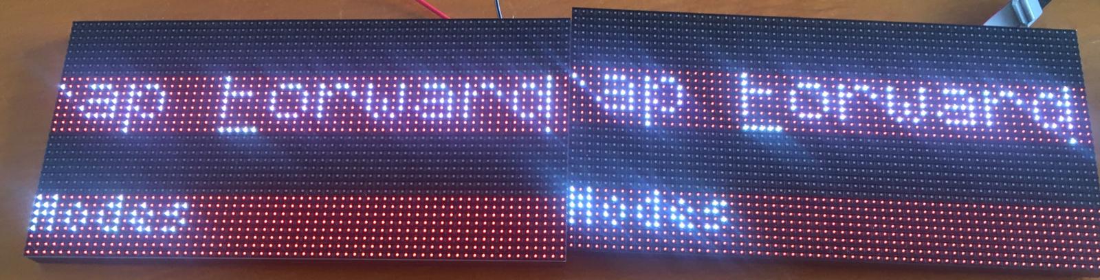
Hi all! I am currently working on a project and trying to connect two 64x32 boards (64x32 RGB LED Matrix - 5mm pitch : ID 2277 : $49.95 : Adafruit Industries, Unique & fun DIY electronics and kits), to form a 64x64 board. Although it says that the scanrate is 1/16, I have tried the FeatureDemo example on one board with SMARTMATRIX_HUB75_64ROW_MOD32SCAN and that worked fine. In the images the boards are next to each other, but I would like to create a square. However, the cables that I am currently using are not long enough for that.
I am using a Teensy 3.2, with the 5th ADDX connected to pin 15 (PTC0). The others are connected to PTC1, PTC2, PTC3 and PTC4. I do not have a SmartLED shield and I hope that I can make it work without it.
I have changed the code as described above, but when I plug in the second screen, it does some weird things (see image). It copies the first screen to the second and only half of the rows are working. Also the letters are not displayed correctly.
Does anyone know what could be wrong?
Thanks in advance!
I have made some changes to the code, I will list them underneath.
FEATURES DEMO
First line is commented out, width, height and kPanelType are adjusted.
// #include <SmartLEDShieldV4.h>  // comment out this line for if you're not using SmartLED Shield V4 hardware (this line needs to be before #include <SmartMatrix3.h>)
#include <SmartMatrix3.h>
#include "colorwheel.c"
#include "gimpbitmap.h"

#define COLOR_DEPTH 24                  // known working: 24, 48 - If the sketch uses type `rgb24` directly, COLOR_DEPTH must be 24
const uint8_t kMatrixWidth = 64;        // known working: 32, 64, 96, 128
const uint8_t kMatrixHeight = 64;       // known working: 16, 32, 48, 64
const uint8_t kRefreshDepth = 36;       // known working: 24, 36, 48
const uint8_t kDmaBufferRows = 4;       // known working: 2-4, use 2 to save memory, more to keep from dropping frames and automatically lowering refresh rate
const uint8_t kPanelType = SMARTMATRIX_HUB75_64ROW_MOD32SCAN; // use SMARTMATRIX_HUB75_16ROW_MOD8SCAN for common 16x32 panels, or use SMARTMATRIX_HUB75_64ROW_MOD32SCAN for common 64x64 panels
const uint8_t kMatrixOptions = (SMARTMATRIX_OPTIONS_NONE);      // see http://docs.pixelmatix.com/SmartMatrix for options
const uint8_t kBackgroundLayerOptions = (SM_BACKGROUND_OPTIONS_NONE);
const uint8_t kScrollingLayerOptions = (SM_SCROLLING_OPTIONS_NONE);
const uint8_t kIndexedLayerOptions = (SM_INDEXED_OPTIONS_NONE);
MatrixHardware_KitV1.h
Added line 4 to define the 5th pin (at PTC0 in Teensy), changed last part of last line: 1 << ADDX_PIN_3 into 1 << ADDX_PIN_4.
SmartMatrix_Impl.h
I added this part: #ifdef ADDX_PIN_4
if (i & 0x10) addressLUT[i].bits_to_set |= (1 << ADDX_PIN_4); #endif
#ifndef ADDX_UPDATE_ON_DATA_PINS
    int i;
    // fill addressLUT
    for (i = 0; i < matrixRowsPerFrame; i++) {
    // set all bits that are 1 in address
    addressLUT[i].bits_to_set = 0x00;
    if (i & 0x01)
        addressLUT[i].bits_to_set |= (1 << ADDX_PIN_0);
    if (i & 0x02)
        addressLUT[i].bits_to_set |= (1 << ADDX_PIN_1);
    if (i & 0x04)
        addressLUT[i].bits_to_set |= (1 << ADDX_PIN_2);
#ifdef ADDX_PIN_3
    if (i & 0x08)
        addressLUT[i].bits_to_set |= (1 << ADDX_PIN_3);
#endif
#ifdef ADDX_PIN_4
if (i & 0x10) addressLUT[i].bits_to_set |= (1 << ADDX_PIN_4);
#endif
    // set all bits that are clear in address
    addressLUT[i].bits_to_clear = (~addressLUT[i].bits_to_set) & ADDX_PIN_MASK;
}
#endif