Hi. Louis.
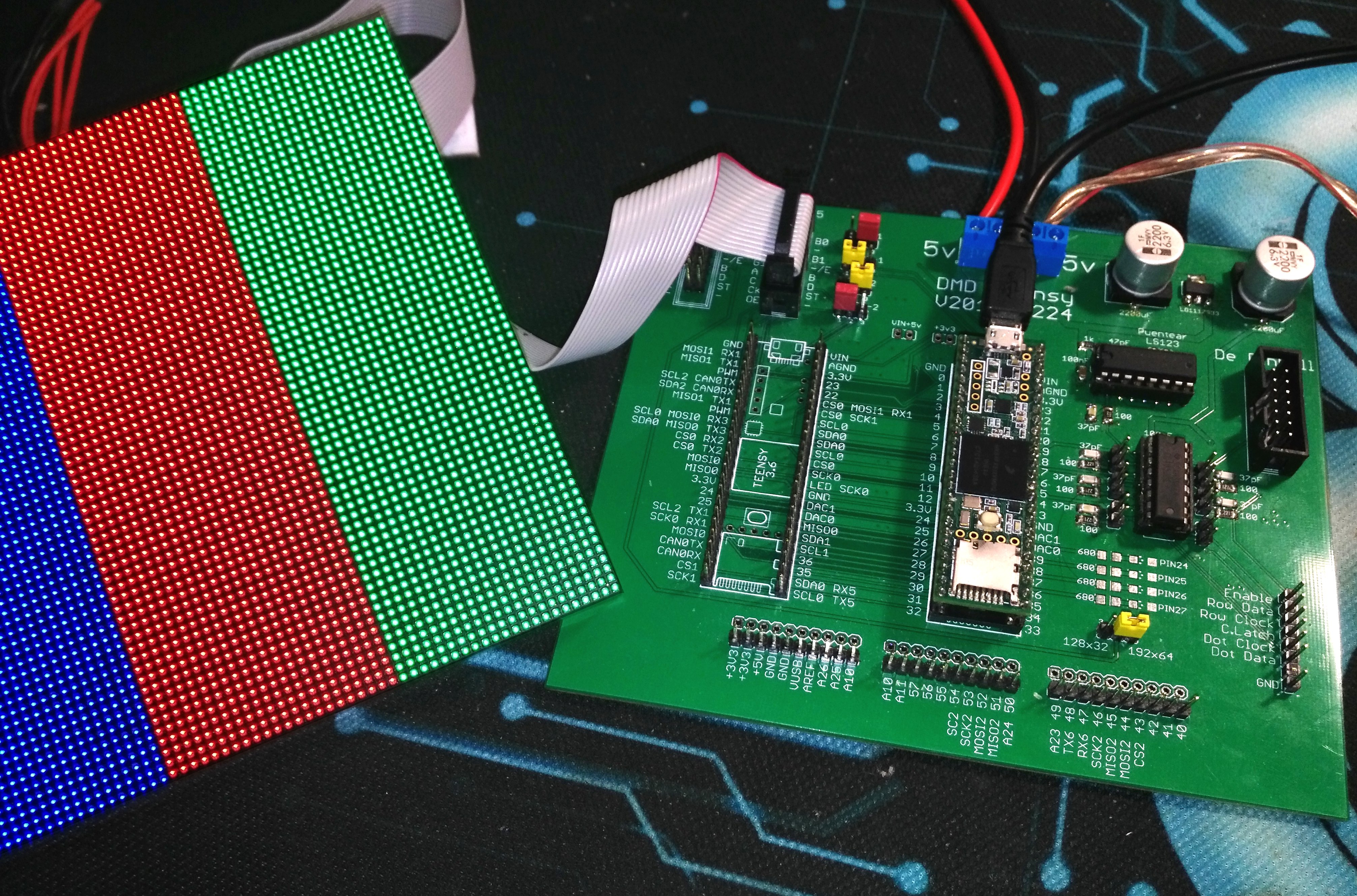
The Chinese have release a new LED panel P2, 64*64, 1/32 Scan, with a new driver chip, the ICN2038S, apparently the panel looks identical, but when connected to Smartmatrix, the screen is completely black.
The Chinese do not provide any information, data sheet, schemes, support is null. So I must apply some reverse engineering to know what happens.
I have ordered a complete set of LINSN boards to test the panels with a PC computer, Led Studio software and the RCG file that defines how to control the Led panel. So I can start it and when the image comes out, capture the signals with a Logic Analyzer to see what the differences are.
In any case, I have looked at the data sheets of both chips, ICN2038 and ICNM2038S, and I think I already know what is different.
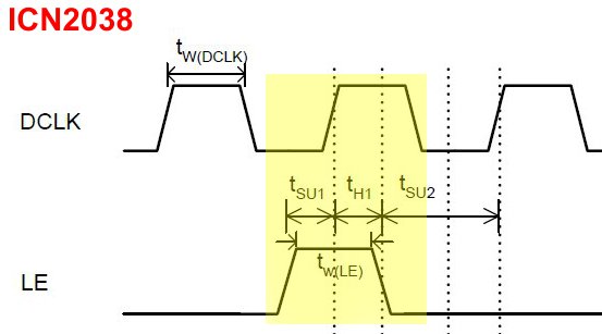
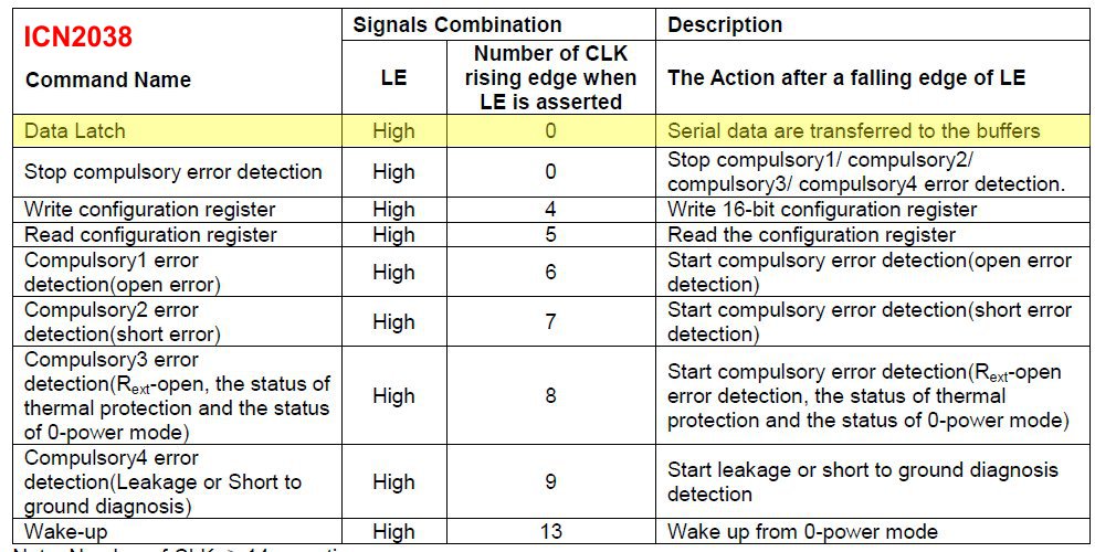
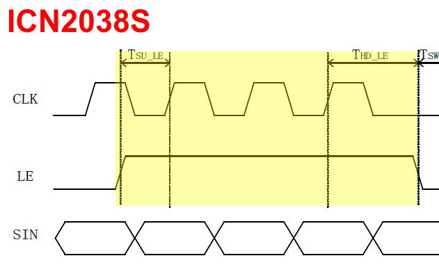
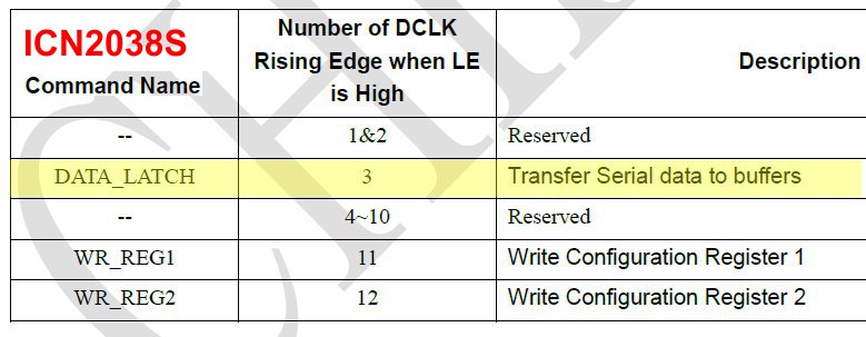
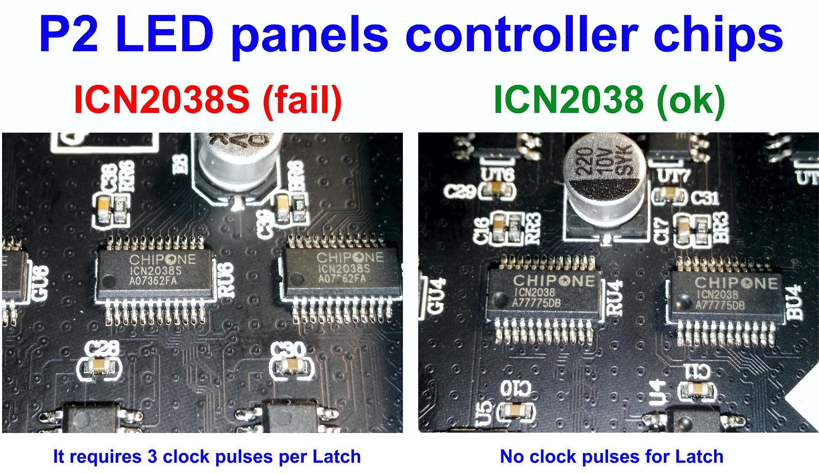
The Latch signal (LE) can be used to send commands in addition to operating as Latch to transfer the input data to the outputs of the shift register. In ICN2038, the LE signal works as Latch when it is at a high logic level for ONE clock pulse, but in the new ICN2038S the LE signal will work as Latch when the signal is at a high logic level for THREE clock pulses.
So, I think this is the difference between these two chips, how many clock pulses LE is at high level.
According to the Chinese, the ICN2038 chip has stopped being manufactured and has been replaced by the ICN2038S. So, if the sources are not modified, will not be able to work with the P2 panels of 64x64, 1/32 Scan. I do not know if this will affect other dot pitch Led panels 64x64. Now I have here 1000 USD in P2 Led panels that fail with Smartmatrix, black screen, all with ICN2038S controller chip.
My question is, where can I modify in the source files how many clock pulses the Latch (LE) signal is at high level ?
I attach captures of the datasheet of both chips, ICN2038 and ICN2038S, both the information in text and in graphic mode with timelines.