This discussion started in a private message conversation with Louis earlier, but is better suited here in the forum so the rest of the community can take part in it and in the end hopefully learn a thing or two
After doing a lot of research I’ve found that for outdoor and high brightness applications, Static Drive is the only way to go. It is way brighter than 1/4, 1/8 etc. scan modes.
Now to the question, is it possible to get support for this in SmartMatrix? If so, how would it be implemented? Can the shield be used for these displays?
Short answer for now: maybe? We need to know more about the interface for the static drive panels. Please post back when you get more information from your manufacturer.
Main questions:
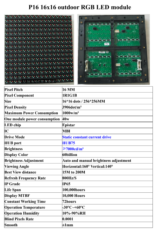
What is the pinout, HUB75?
How is the OE signal used on the panels?
Followup question for me once we know: can the SmartMatrix Library’s OE signal use where a row’s brightness is modulated directly after being shifted out be adapted to a static drive panel where presumably OE controls all the rows at once?
Is there any thermal protection that needs to be implemented in software beyond just lowering the global brightness? If all the LEDs could be on all the time, the panel could get very hot.
According to the manufacturer they use the MBI5124. I’ve not doublechecked this on the displays I have but I will asap. If they use another IC I will post the update here in the thread.
Yes, they use HUB75
This is something I cannot answer and the sales rep of the manufacturer could not answer either. I will try again to get some info regarding this.
Thermal protection no, I don’t think so. Since the displays are made to be outside and “unprotected” (i.e no encapsulation) the displays will hopefully get cooled by the air circulating in front of each module. Also, the pixel density is much lower than a P10 or lower (of course)
Thermal protection … the displays will hopefully get cooled by the air circulating in front of each module
I wouldn’t depend on that for cooling. If I recall correctly this video shows the cooling system that is used on the IC side of these displays in a commercial outdoor system. These panels might also be static, and video might also describe how to drive these. (I don’t have time to watch it right now)
You are probably right, the IC side will most likely need some kind of cooling. But as of now, that is not a concern. Nice video though, a lot of detailed info I’ve not found online before. Thank you!
Thanks for the photo. There’s no marking of pinout on the PCB like some panels have. There could be 2-5 Address lines on a HUB75 pinout. Can you ask the vendor how many there are on this panel?
Sorry, I didn’t zoom in and didn’t see the fine line silkscreen that shows the pinout. It’s there, and it shows an A,B,C address line, so it’s /8 scan.
I received the sample static panel you sent and I hooked one up to a SmartLED Shield with Teensy 3.6, and tried driving it with the kPanelType = SMARTMATRIX_HUB75_16ROW_MOD8SCAN setting which matches this HUB75 pinout and the panel size. I can drive all the LEDs when using fillScreen(), but the order that the pixels are loaded seems different from usual, as if I draw a diagonal line from one corner to the other, there’s no line, but blocks of pixels in the middle. Without having any documentation I’ll have to play around with this more to try to determine an order to loading the pixels.
Haha yeah, I asked the manufacturer and they said the same thing about the silkscreen.
/8 scan? As I’m new to this, this is really confusing. I thought they were supposed to be “static”? Or are we talking about different things?
What is the mapping of pixels on the panel to the order of RGB data shifted in through the HUB75 connector?
How are the three address lines used?
Usually having three address lines means the panel is /8 scan: you shift in two rows of data at a time (through RGB1 and RGB2 pins), and it is displayed on the rows selected with the address lines. Maybe the address lines aren’t actually used on these static panels, though they are shown on the silkscreen. The issue I’m seeing when trying to drive a single pixel at a time with SmartMatrix Library set in /8 scan mode is the pixel displayed in 8 different places. Maybe I need to shift out all the pixels at once, and just ignore the address lines. That’s the next thing I’ll try.
Turns out the address lines are unnecessary, you can address all pixels without changing the address lines, by treating it as a 128x2 /1-scan panel. The pixels are grouped in 4x4 blocks however, so it’s not straightforward to map the 128x2 virtual display inside SmartMatrix Library to the 4x4 blocks inside the 16x16 panel.


")