Odd Colour Rendering (GS6238S fix)

Hi,

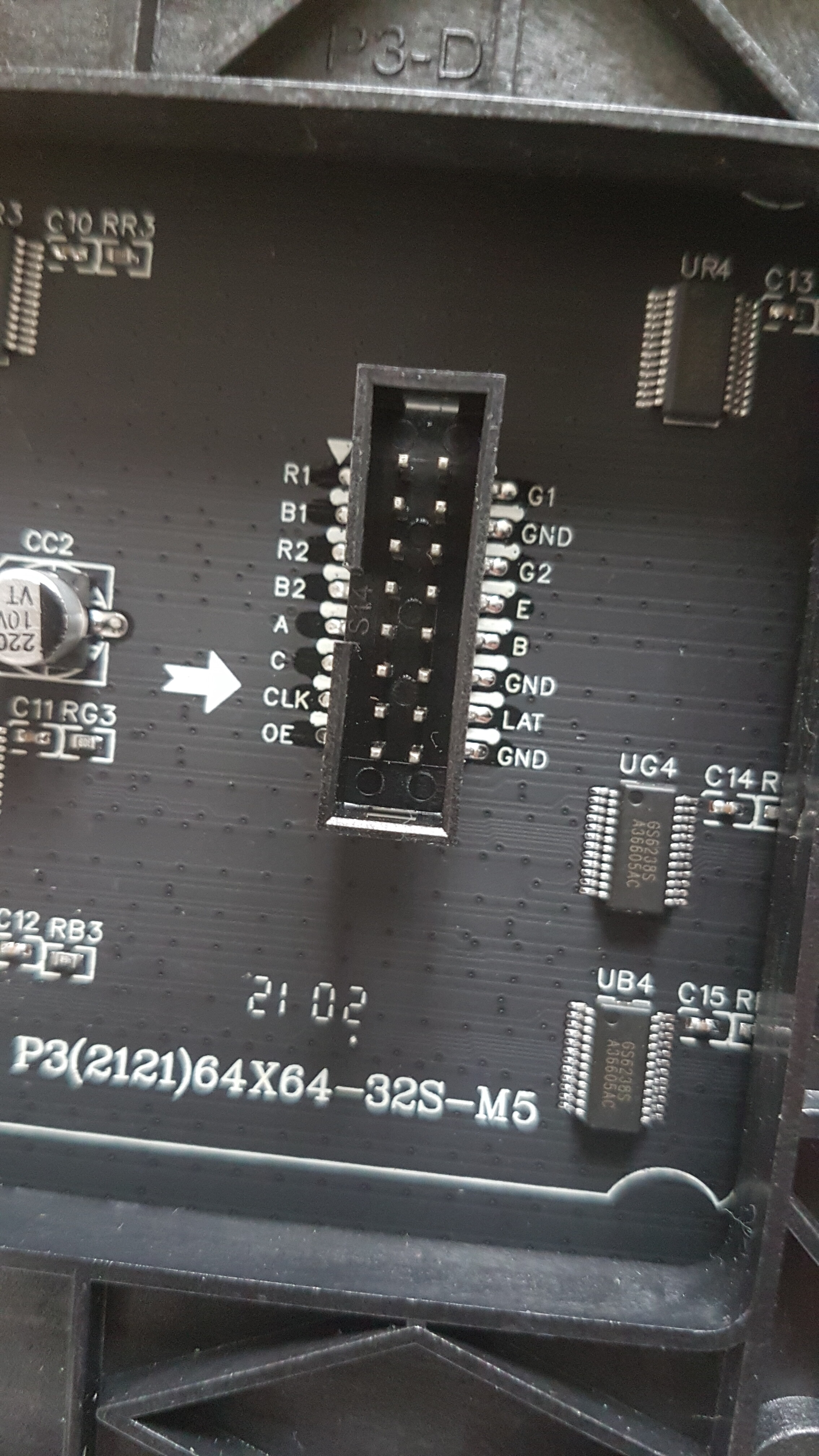
I hope you can help me with a problem I seem to be having with a p3 64x64 1/32 panel. I’m using a Teensy 4.1 with the SmartMatrix v5 shield, and I’m using PlatformIO with version 4.0.3 of the SmartMatrix library.

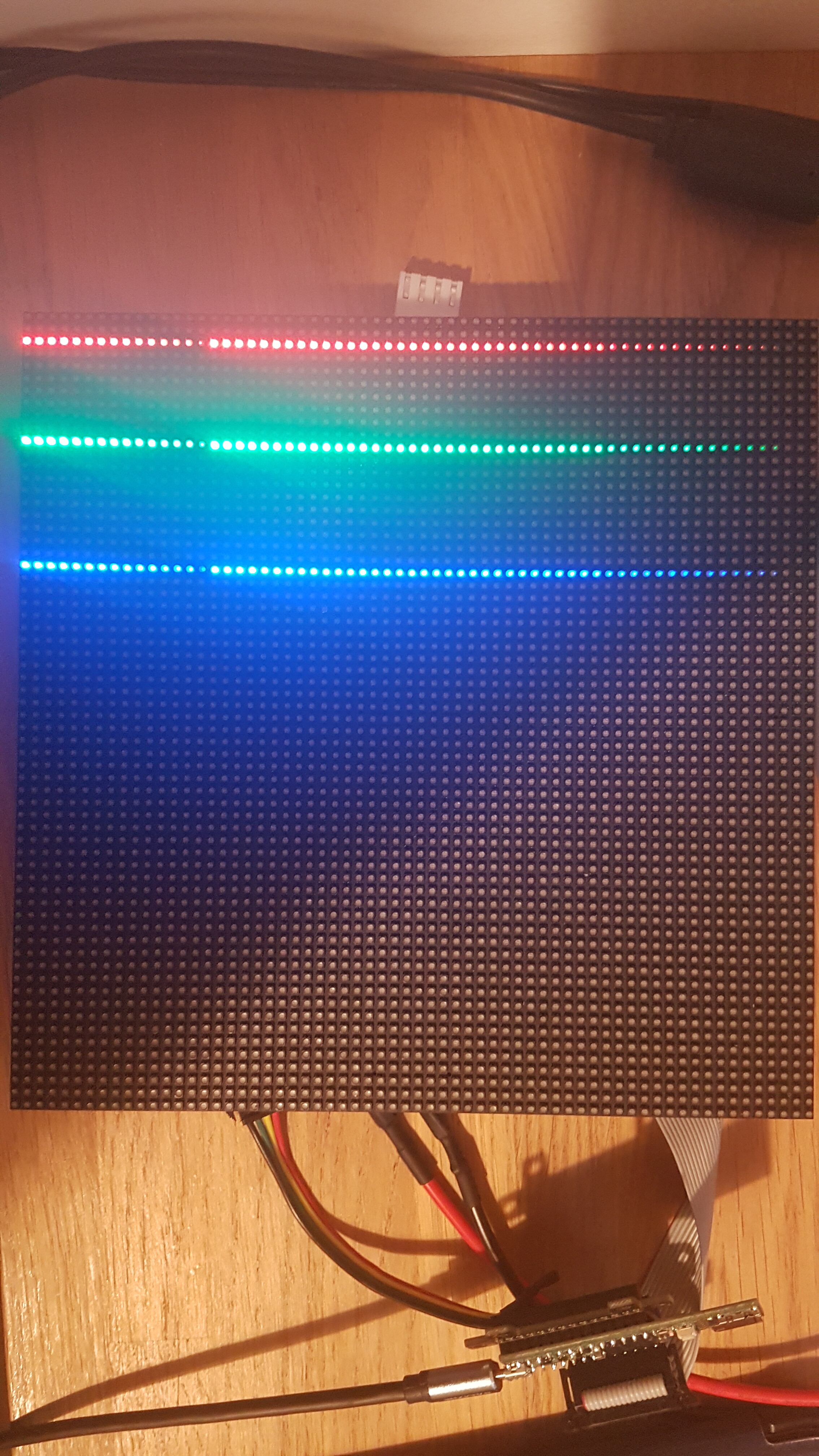
The panel worked straightaway with this configuration and I was able to draw on it very easily. It seems very stable and works almost as expected. The only issue I have is with the colour rendering. It seems that the MSB of all three RGB values is ignored, and bit 6 (of an 8-bit colour channel) effectively becomes the MSB instead. The effect is that at a value of 128, the colour turns off.

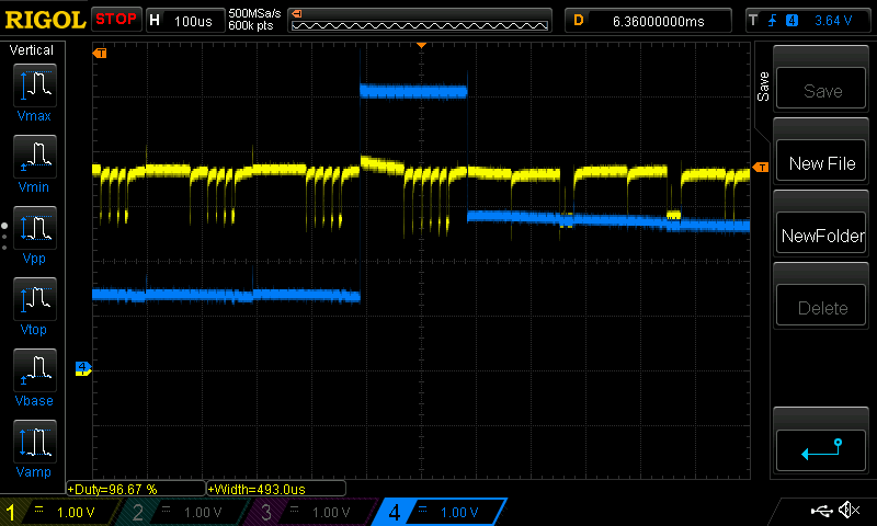
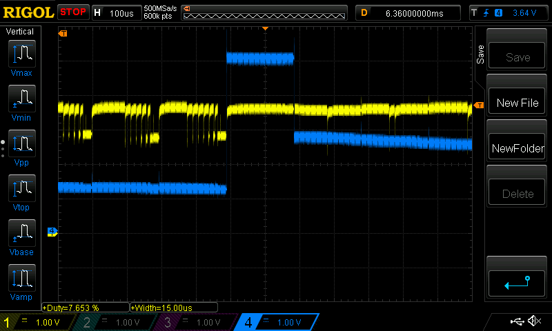
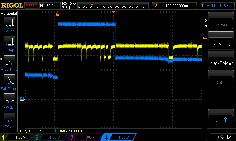
Here’s a demonstration of it:

The code that generated this is:

#include <MatrixHardware_Teensy4_ShieldV5.h>        // SmartLED Shield for Teensy 4 (V5)
#include <SmartMatrix.h>

#define COLOR_DEPTH 24                  // Choose the color depth used for storing pixels in the layers: 24 or 48 (24 is good for most sketches - If the sketch uses type `rgb24` directly, COLOR_DEPTH must be 24)
const uint16_t kMatrixWidth = 64;       // Set to the width of your display, must be a multiple of 8
const uint16_t kMatrixHeight = 64;      // Set to the height of your display
const uint8_t kRefreshDepth = 36;       // Tradeoff of color quality vs refresh rate, max brightness, and RAM usage.  36 is typically good, drop down to 24 if you need to.  On Teensy, multiples of 3, up to 48: 3, 6, 9, 12, 15, 18, 21, 24, 27, 30, 33, 36, 39, 42, 45, 48.  On ESP32: 24, 36, 48
const uint8_t kDmaBufferRows = 4;       // known working: 2-4, use 2 to save RAM, more to keep from dropping frames and automatically lowering refresh rate.  (This isn't used on ESP32, leave as default)
const uint8_t kPanelType = SMARTMATRIX_HUB75_64ROW_MOD32SCAN;   // Choose the configuration that matches your panels.  See more details in MatrixCommonHub75.h and the docs: https://github.com/pixelmatix/SmartMatrix/wiki
const uint32_t kMatrixOptions = (SM_HUB75_OPTIONS_C_SHAPE_STACKING | SM_HUB75_OPTIONS_BOTTOM_TO_TOP_STACKING); //(SM_HUB75_OPTIONS_NONE);        // see docs for options: https://github.com/pixelmatix/SmartMatrix/wiki
const uint8_t kIndexedLayerOptions = (SM_INDEXED_OPTIONS_NONE);
const uint8_t kBackgroundLayerOptions = (SM_BACKGROUND_OPTIONS_NONE);
const uint8_t kScrollingLayerOptions = (SM_SCROLLING_OPTIONS_NONE);
const rotationDegrees kRotation = rotation0;

const int defaultBrightness = (100*255)/100;        // full (100%) brightness
//const int defaultBrightness = (15*255)/100;       // dim: 15% brightness
const int defaultScrollOffset = 6;
const rgb24 defaultBackgroundColor = {0x00, 0, 0};

// Teensy 4.0 has the LED on pin 13
const int ledPin = 13;

SMARTMATRIX_ALLOCATE_BUFFERS(matrix, kMatrixWidth, kMatrixHeight, kRefreshDepth, kDmaBufferRows, kPanelType, kMatrixOptions);
SMARTMATRIX_ALLOCATE_BACKGROUND_LAYER(backgroundLayer, kMatrixWidth, kMatrixHeight, COLOR_DEPTH, kBackgroundLayerOptions);

void setup() {
// initialize the digital pin as an output.
pinMode(ledPin, OUTPUT);

Serial.begin(115200);

matrix.addLayer(&backgroundLayer); 
matrix.begin();

matrix.setBrightness(defaultBrightness);
matrix.setRotation(kRotation);

backgroundLayer.enableColorCorrection(true);

// clear screen
backgroundLayer.fillScreen(defaultBackgroundColor);
backgroundLayer.swapBuffers();
}

void loop() {
   EVERY_N_MILLIS(50)
   {
    for(uint8_t i=0;i<kMatrixWidth;i++)
    {   
        uint8_t v=i<<2;
        backgroundLayer.drawPixel(2,i,{v,0,0});
        backgroundLayer.drawPixel(10,i,{0,v,0});
        backgroundLayer.drawPixel(20,i,{0,0,v});
    }
    backgroundLayer.swapBuffers(false);
    }
}

I’ve tried using 48-bit colour depth, switching colour correction on/off (without colour correction, the gradient resets half way along the row rather than as shown in the picture), increased refresh depth to 48, reduced DmaBufferRows to 2, and none of these made a difference. I’ve been investigating inside the library to see if there was anything amiss, but I can’t seem to find a reason for this behaviour. I’ve also tried changing kMatrixOptions to SM_HUB75_OPTIONS_NONE, and that doesn’t help either (I will be using 4 panels connected together in the final project).

Does anyone have any thoughts on what might be causing this?

Thanks for looking.

welshcoder

If it’s in any way reassuring, I put your code on my T4.1 and got the results I expected: three smooth ramps with no discontinuities. The only notable difference is I used the Arduino IDE rather than PlatformIO. Do you get the same results using Arduino IDE?

Do the results change if you use rotate90? If it’s not simply the same image rotated, that image might possibly hold a clue.

Thanks for checking - that is reassuring!

I dusted down my copy of the the Arduino IDE and ran the above code through that, and I got the same results as I did with PlatformIO.

I tried rotation0, rotation90, rotation180 and rotation270, and they all produced the same effect as shown, but rotated.

Since I posted, I manipulated the function fillRefreshRow in Layer_Background_Impl.h so that the the rgb48 values in refreshRow[i] are shifted by 1 bit to the left. I used
refreshRow[i]=rgb48(refreshRow[i].red>>1,refreshRow[i].green>>1,refreshRow[i].blue>>1);
after line 120 to achieve this (with colour correction on). This produced the desired smooth ramps of colour. It’s not perfectly smooth (the picture below shows some effect of stepping about a third of the way down), but much better than it was.

So, it’s a fix of sorts, but I’m not entirely sure why the issue is happening in the first place.

Forgot to add, the panel uses GS6238S, TC7262BJ and MW245B chips, in case that makes a difference.

Ah! You’re seeing better results with GS6238S than is expected. :slight_smile:

Have you had any luck finding a datasheet for that chip?

Interesting - the plot thickens! Buying these panels at a reasonable cost seems to be such a gamble! Especially since there’s an error on the silkscreen by the connector on the panel I’ve got.

I saw the ‘E’ line, I thought all is fine, and then I noticed that the ‘D’ line is missing and ‘GND’ is printed in its usual spot. However, that is a misprint - it is not connected to ‘GND’ and is, in fact, the ‘D’ line! So, I plugged it all in and it worked on first power up!

Because I had a success with this panel, I bought 4 more from the AliExpress vendor and they should arrived shortly. I asked for panels from the same batch as the one in the picture, so fingers crossed.

Unfortunately, I couldn’t find a datasheet for the GS6238S. I’ll keep on looking though, just in case.

I thought I would share these catures I got with my scope when probing the panel… The measurements were taken without the bit shift solution I gave above.

To get this, I probed the pins on the LED themselves. The blue trace appears to be the anode (?) and the yellow trace seems to be the cathode (?) of the red LED. The display is showing the gradient once again.

The LED I was measuring had a value of rgb24(63,0,0), and sure enough, you can see the 6 bits within the pulse. The next LED had a value of 65. Notice the long pulse for the 7th bit. The effect of this is that there is a noticable step increase in the intensity from 63 to 65.

Looking further along the gradient, and I get to rgb24(128,0,0) and I get this:

Looking at the previous LED, you can see that there is 6 normal pulses and 1 long one for the 7th bit. When the value turns to 128 during the blue pulse, the 8th bit is missing completely.

I’m coming to this from a point of ignorance of how exactly these displays work, so apologies if this is expected behaviour, but I don’t think it is. I don’t know if it’s possible to initiate the bit stream a little earlier, and I’m not entirely sure which setting does that (I’ve changed all the settings in MatrixHardware_Teensy4_ShieldV5.h, but they don’t seem to have an effect on this problem).

Any thoughts on this? I can probe more signals if necessary.

I did ask the AliExpress vendor if they have a datasheet for the GS6238S chip, but they don’t unfortunately. The four other panels arrived the other day and they all work great…apart from this issue!

1 Like

Fixed!

The solution was to modify MSB_BLOCK_TICKS_ADJUSTMENT_INCREMENT on line 44 from (TICKS_PER_ROW/512) to (TICKS_PER_ROW/64) in MatrixTeensy4Hub75Refresh_Impl.h. I now get the correct 8 bits showing as you can see below (the value during the pulse is 127, and the next one is 128).

I don’t know if this is the only fix required that will make displays with GS6238S chips work more reliably with SmartMatrix, but it seems to work for me anyway. Hopefully anyone else coming across this problem will find this information useful.

1 Like

That’s very odd. I wouldn’t expect that parameter to make a difference.

Could you enable the “debugging table” in the calculateTimerLUT function in that source file? Just change the “#if 0” to “#if 1” on line 227 and let us know what prints out, before and after applying your fix.

Sure, no problem.

Here is the output with the fix in place:

Refresh rate: 158 (Min/Max: 18/158)
Max brightness limited to 15%
bitplane 0: period: 1226: ontime: 1226
bitplane 1: period: 1226: ontime: 1225
bitplane 2: period: 1226: ontime: 1224
bitplane 3: period: 1226: ontime: 1222
bitplane 4: period: 1226: ontime: 1217
bitplane 5: period: 1226: ontime: 1208
bitplane 6: period: 1226: ontime: 1190
bitplane 7: period: 1226: ontime: 1153
bitplane 8: period: 1226: ontime: 1079
bitplane 9: period: 1226: ontime: 931
bitplane 10: period: 1226: ontime: 636
bitplane 11: period: 1226: ontime: 46

And here is the output with the original value:

Refresh rate: 158 (Min/Max: 18/158)
Max brightness limited to 17%
bitplane 0: period: 1226: ontime: 1226
bitplane 1: period: 1226: ontime: 1225
bitplane 2: period: 1226: ontime: 1224
bitplane 3: period: 1226: ontime: 1221
bitplane 4: period: 1226: ontime: 1216
bitplane 5: period: 1226: ontime: 1206
bitplane 6: period: 1226: ontime: 1185
bitplane 7: period: 1226: ontime: 1144
bitplane 8: period: 1226: ontime: 1062
bitplane 9: period: 1226: ontime: 898
bitplane 10: period: 1226: ontime: 570
bitplane 11: period: 1322: ontime: 9

In both cases, LATCH_TIMER_PULSE_WIDTH_NS = 120, LATCH_TO_CLK_DELAY_NS = 400 and FLEXIO_CLOCK_DIVIDER = 26. Also, I tried with a divisor of 32 and 16, and they work as well. It stops working completely when the divisor is 8, and the original problem reoccurs when the divisor is 128 or above.

Just a bit more info on this.

The fix only works for certain values for the RefreshDepth. In the examples above, it was 36. It also worked with a value of 30, but not 33 or 24. The only (2^n) divisors that worked for RefreshDepth = 24 were 2 and 4, but the lines were very dim.

When the RefreshDepth = 48, only divisors that worked were 4 and 8 (which resulted in a very dim display - barely visible).

I haven’t gone through all the combinations, but the pattern that I have seen is that when it works, the period of bitplane 11 is the same as all the others. It stops working when that period is different (higher) to the others.

Teensy 4.1 should be capable of far greater than 158 FPS at 64x64 and 36bit refresh. That makes me think there’s a bug in the LUT calculation somewhere. Or were you running more than 64x64 pixels in that test?

Is it possible that PlatformIO runs the chip clocks at a different speed than Arduino IDE does?

Having the MSB bitplane period be longer than the others is expected behavior and should not be causing these issues - the pulse width should still be 2x the next smaller bit.

I was running a 128 x 128 display (4 off 64 x 64 in square configuration) - sorry, I forgot to mention that.

The default speed for the Teensy in PIO is 600 MHz, and I haven’t changed that.

Ok, fair enough - it was just something I happened to notice. I’ll keep trying different things to see if I can find a reliable common factor to what’s causing the problem.

What happens if you reduce defaultBrightness?

Ah! That does fix it!

I changed the defaultBrightness from 255 to 254, and it worked. I changed the divisor back to 512 and it still works with all the RefreshDepth values I’ve just tried.

Thank you!

Nice!

I’d guess the problem here is the GS6238S has slightly different timing behavior. When you’re at full brightness usually the MSB has the OE pulse edge come very close to the LAT pulse. That’s not been a problem with other chips, but maybe this chip doesn’t like it and somehow it causes the MSB pulse to be inverted (?). Reducing the brightness has the effect of adding some padding between the pulses. Glad to hear that it fixes the problem.

By the way - with a 128x128 matrix I think you are probably not getting any benefit from 36bit color depth. I would go to a lower color depth (30 or even 24) to get an improvement in brightness and refresh rate.

Yes, I see what you mean, and that makes sense. Hopefully it is a sign that the GS6238S can be supported with a very slight modification to the configuration.

Thank you for the advice - I’ve just changed that setting and it does make it brighter, so I’ll go with that.

If you need me to investigate anything else related to displays using these chips, just let me know.