The standard SPI port (pins 10-13) is blocked by the HUB75 panel driver. There was no way around that. But there are two more hardware SPI ports on Teensy 4.0 and 4.1 and the driver and shield do not interfere with them. SPI1 uses pins 0,1,26,27 which are free. And if you are not using an SD card, there is also SPI2 which uses the DATA1, DATA0, CLK, and CMD pins of the SD card interface. These are numbered as pins 34-37 on Teensy 4.0, renumbered as pins 42-45 on Teensy 4.1.
On Teensy 4.0, you will need to carefully solder wires to the very small SMT pads on the bottom side to access pins 26-27 and 34-37.
On Teensy 4.1, pins 0,1,26,27 are easy to access on the external headers. Pins 42-45 are only available through the SD card connector so you would need something like this Sparkfun microSD breakout to access them.
Unfortunately, I need the SD card, and then only SPI1 is free. Since I need a second SPI for my applications, I was thinking of being able to use Flexio to emulate a new SPI port, I don’t have experience with Teensy 4 yet, but I think this is possible. It was to know if there are free pins that do not affect the operation of Smartmatrix, with which to be able to emulate a new SPI (with DMA) configuring it with Flexio.
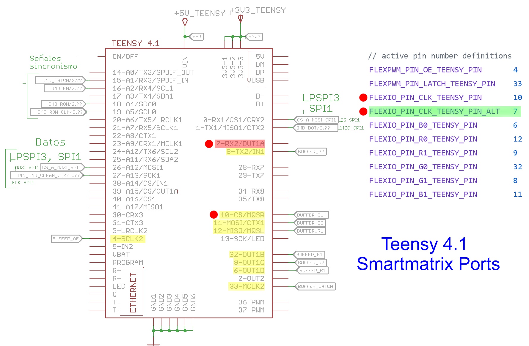
I was reviewing the connections in my schematic and at first I found it confusing because pin7 did not have it assigned, I was going to ask you about this, but reading the source I think pin7 is to be used as an alternative to pin10, that is, only one would be used of the two. This is so ?.
As an alternative to being able to emulate a new SPI with Flexio, reviewing the schema and the datasheet, I think I could remove the QSPI, boot from SD, and use LPSPI2 for my application.
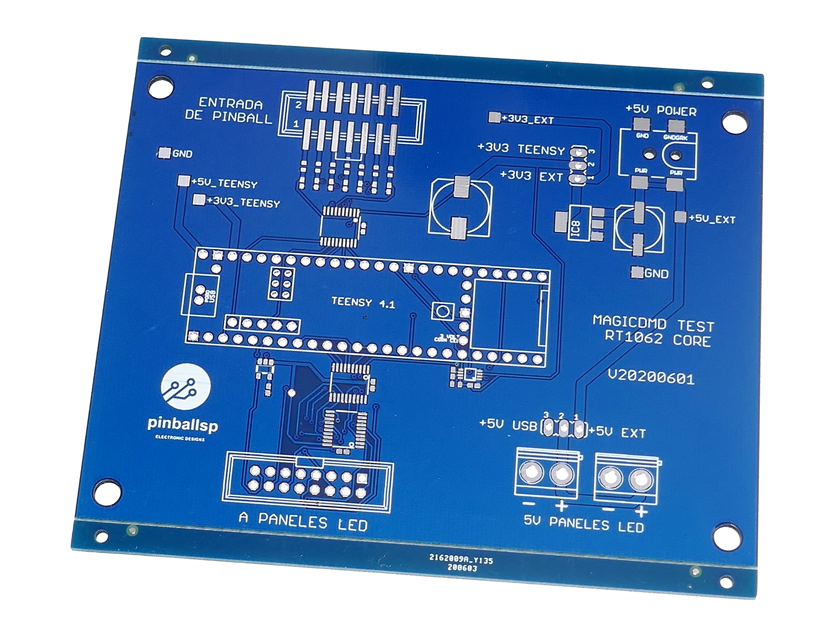
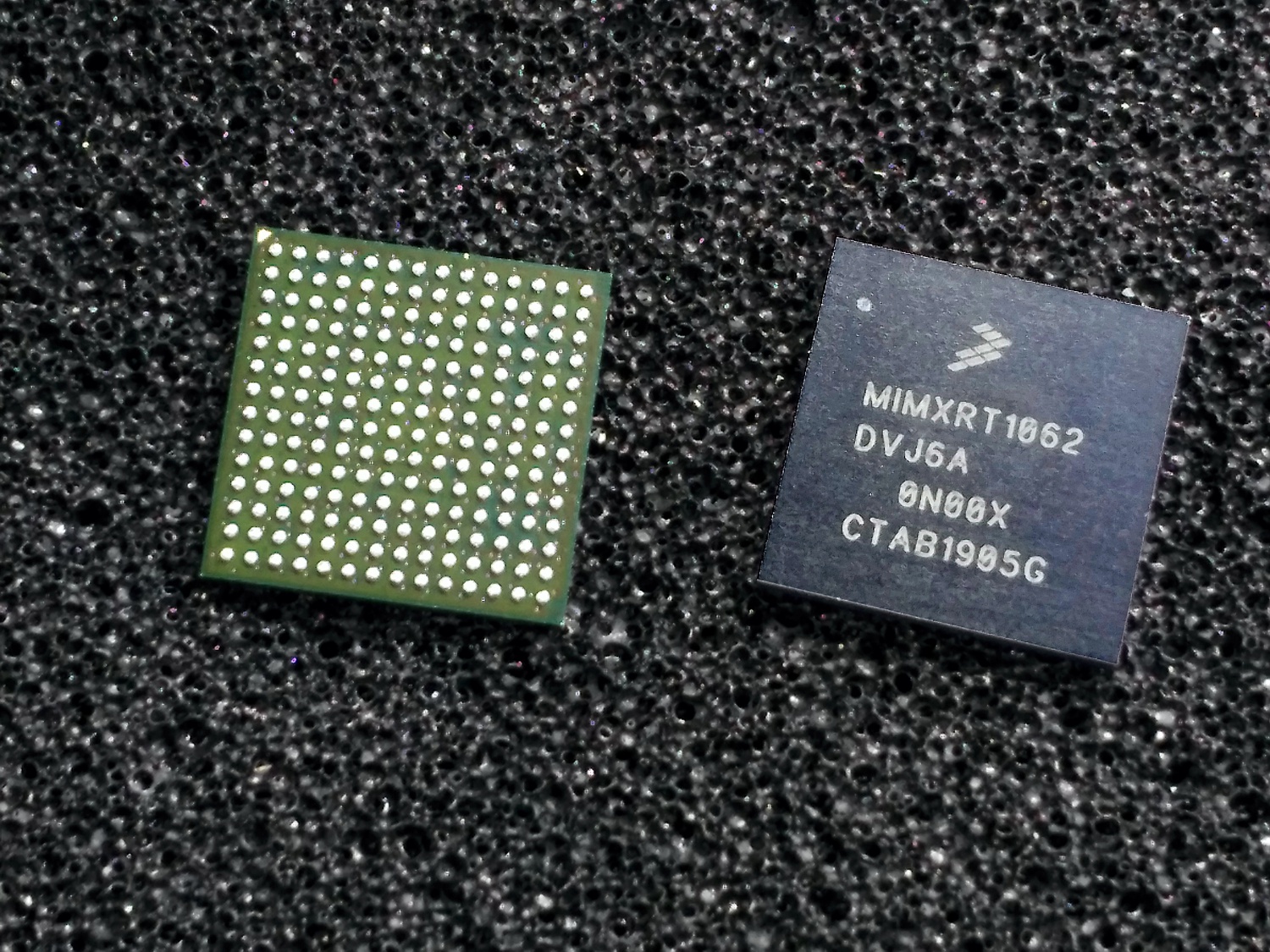
My final design will be with my own board that will install the RT1062 microcontroller, now I only use Teensy for testing.
If you need to use the SD card pins for smartmatirx, can the sdcard be plugged into other GPIO with bit banging?
Otherwise another option for less than $20 is an ESP32 with 8MB of PSRAM and 16MB of flash, which is enough to store some amount of graphics in FatFS (or SPIFFFS), with no sdcard requied.
I need the SD card by SDIO 4bit, I can’t remove it. The only thing I thought is to remove the QSPI to use LPSPI2, and boot from SD card. However, I think the ideal would be to be able to emulate a new SPI port using Flexio, there are enough free pins on Flexio1 and Flexio2 to be able to use it with DMA.
In MCUxpreso for the RT1062, there are examples of source code emulating an SPI with Flexio and DMA, but for now I can’t find anything for Teensy 4. In the Kurte library there is an example, but quite basic, I think it doesn’t use DMA.
I have never considered using ESP32, I prefer the ARM world for compatibility and portability between manufacturers, also the RT1062 is much more powerful than the ESP32 processor.
@pinballsp: since you’re not using the SmartLED Shield and you’re developing custom hardware, you could use a different pinout instead of the one I chose. I actually think it is possible on Teensy 4.1 to select the LED matrix pins to not conflict with any of the hardware SPI ports: you can use pins 7,8,9,32,36,37 for RGB data, pin 6 for CLK, and pins 2&3 for LAT and OE. There are other options too: CLK could be either 34 or 35 and LAT&OE could be 4&33 or 28&29. The ordering of the RGB pins and the LAT/OE pins are not important. I can share a spreadsheet that details all the possibilities if people are interested.
We thought it would be better to maintain Teensy 4.0 compatibility for the new SmartLED Shield design, which unfortunately requires blocking the main SPI port.
To answer your question, yes it is possible to emulate SPI with FlexIO1 while the LED matrix driver runs on FlexIO2. In fact that’s exactly what Louis implemented for APA102 LED driving. The available FlexIO1 pins are 2,3,4,5,33. But I don’t know how hard it will be for your application.
Thanks easone, the options look very interesting.
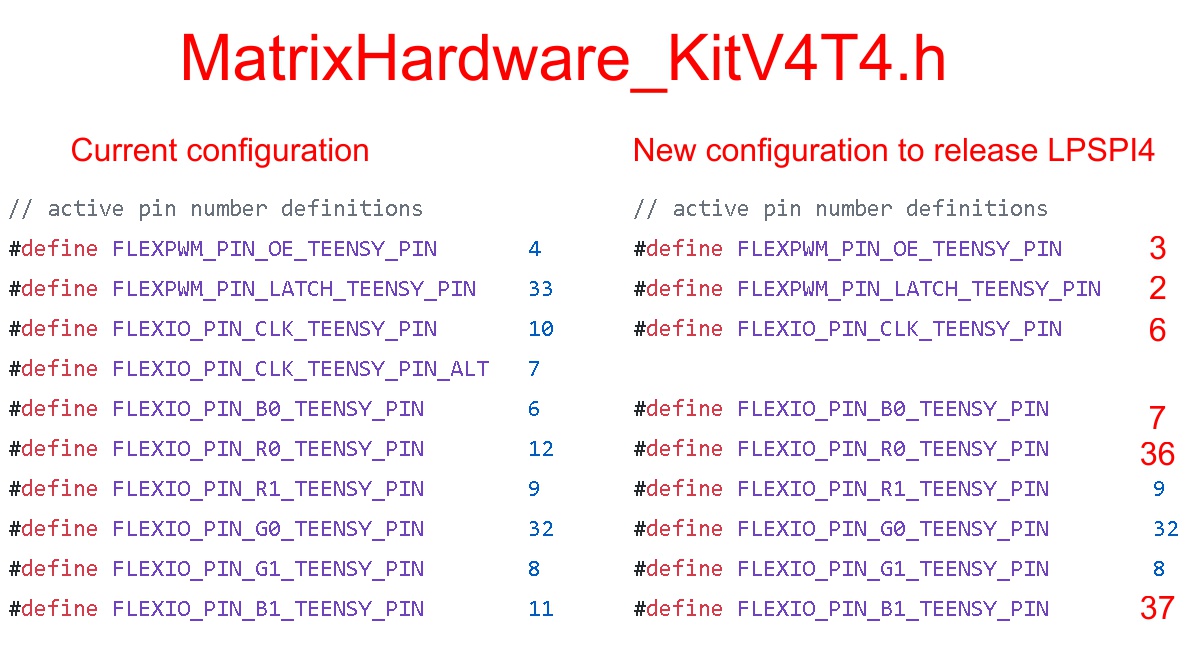
If I can modify the pin assignment, to release the LPSPI4 port, using other Flexio2 pins for Smarmatrix, it is perfect for me.
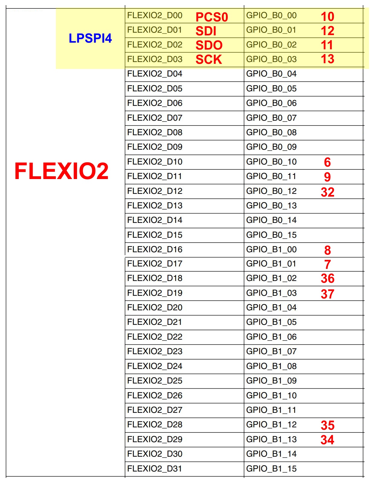
So I understand that I just have to edit the MatrixHardware_KitV4T4.h file and modify the pin assignment. I was looking at the available ones in Teensy 4.1 for Flexio2 and I created these tables.
That should work - you only have to change the pin numbers defined in that header. The one time setup should configure everything automatically for you. Hopefully.
Here is the rule for selecting data/CLK pins. For the driver to work, you need to choose a contiguous group of 16 FlexIO2 pins, and choose your 6 data signals from within that group; CLK can be inside or outside that group but needs to be the lowest or highest pin (in terms of the hardware FlexIO2 assignments).
It’s not foolproof, but there is a configuration validation check that will print an error message to Serial if there is a problem with the pin numbers.
Hi easone.
So there is something that I think is wrong in the new selection of pins, if I have understood correctly what you indicate.
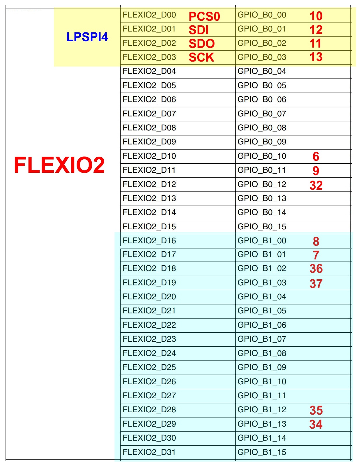
In Flexio2, we would have to choose pins from the same contiguous 16-pin block, that is, block1 D00 to D15, or block2 D16 to D31 (according with picture attached). CLK can be chosen from any of the two blocks but it must be the first or last.
So the selection of pins 7, 8, 9, 32, 36, 37, for RGB, would not be correct, since pins 9 and 32 are in the first 16-bit block, and the rest of the pins are in the second block. 16-bit Flexio. Also the original pin configuration would be incorrect since pins 6, 9, 11, 12, 32 are on block1 and pin 8 is on block2. Is this correct ?.
So a correct selection of pins for RGB would really be this? 7, 8, 34, 35, 36, 37 of Flexio block2, and pin 6 for CLK of Flexio block1.
There is no need for the 16 pin block to start at pin D00 or D16. FlexIO allows you to pick any pin as the start of the 16 pin block, so you can choose D01-D16 or D11-D26.
Apologies if I’m missing something obvious here, but I’m stumped.
I got Louis’ OshPark adapter and a 4.1 a few days ago, and I pulled down the “teensy4” branch from the repo. I can’t seem to get it to compile at all. Here’s what I’m seeing:
In file included from [fullpath]\Arduino\libraries\SmartMatrix-teensy4\src/SmartLEDShieldV4.h:5:0,
                 from [fullpath]\Local\Temp\arduino_modified_sketch_373068\FeatureDemo.ino:6:

[fullpath]\Arduino\libraries\SmartMatrix-teensy4\src/SmartMatrix3.h:44:19: error: No MatrixHardware*.h file included - You must include one at the top of your sketch

 #pragma GCC error "No MatrixHardware*.h file included - You must include one at the top of your sketch"
I was able to roll back my library to “master” and switch over to a Teensy 3.2 on the same hardware which compiled with a few warnings. For reasons I can’t understand, the “teensy4” branch gives me that weird error. (That forward slash in the error message path looks ominous fwiw)
I’m on Arduino 1.8.12 / Teensyduino 1.52 if that helps. Please advise.
Right now, with the Teensy4 branch, you need to include one of the following headers before you include SmartMatrix:
MatrixHardware_KitV4T4.h (if you are using jumpers to rewire the shield)
MatrixHardware_T4Adapter.h (if you are using the OSHpark adapter)
SmartLEDShieldV4.h is not used anymore.
We are testing a new version of the shield designed specifically for T4.x, which will probably have a different named header.
I need to bring the examples in the teensy4 branch up to date to show how to include the MatrixHardware*.h file. Most examples in the NT branch show how to include the file. I’ll merge these over to the teensy4 branch at some point, hopefully soon:
Thanks, all. I got it working by using the proper include. I’m going to order a teensy 4.1 so I can use the onboard SD card. I’ll put it thru its paces soon.
I am also preparing my own board for testing, I already received the Teensy 4.1, and today the PCB of my own board with a different pin assignment to have the LPSPI4 port free.
I also ordered some 8MB PSRAM chips, to add two to Teensy 4.1, so I will have an extra 16MB of RAM. Any variable or array can be assigned to that PSRAM by adding the EXTMEM prefix to the variable definition. PJRC Store
I have yet to finish another design of my own board with the RT1062 microcontroller, instead of using a Teensy, but first I want to try the Teensy because it is easier. It will be my first board with BGA chips.
There’s hasn’t been any updates in a while but there’s a lot going on:
The SmartLED Shield for Teensy 4 prototypes were manufactured, received, tested, and they’re working great
Eric has been making improvements to the Teensy 4 HUB75 code
I’ve been working on other SmartMatrix Library code aiming to a SmartMatrix Library 4.0 release
I’m improving the Animated GIFs code, turning Adafruit’s adaptation of the AnimatedGIFs sketch into a generic GifDecoder Library with SmartMatrix Library examples
I’ve started working on a Crowd Supply campaign for the SmartLED Shield for Teensy 4, and hope to launch this month, the sooner the better
The Teensy 4 is really powerful, and able to push a lot of pixels to the panels. I’m going to need to update SmartMatrix Library to make sure some of the uint8_t types used in older code (when any dimension of the display approaching 256 seemed far out of reach), are replaced with uint16_t so displays wider/taller than 256 pixels can be driven. 128x128 pixel Animated GIFs can be decoded and driven to a 128x128 36-bit color 240Hz refresh display at 100% speed.
From what I’ve tested so far, 128x128 with high color depth and high refresh rate doesn’t seem to be pushing the limits of the Teensy 4. (edit: see next post)
What does push the limits? @marcmerlin I tried your use case of 128x192 pixels, wanting a high refresh rate and willing to sacrifice color depth. Best it can do so far is 24 bit color, 130 Hz refresh, decoding the 128x192 GIF I tested at 77% of full speed. Eric added some code to lower refresh rate below 24 for the Teensy 4, but for some reason I get lower refresh rate with that code. Not perfect, but at least promising!
Looks like I made a mistake while testing and 128x128 isn’t actually able to do 240Hz refresh.
Summary of max refresh seen when testing GIF (128x128) decoder sketch with matrix.setRefreshRate(240):
128x128/32 36-bit color: 157Hz
128x128/32 24-bit color: 202Hz
128x192/32 24-bit color: 130Hz
96x96/32 36-bit color: 240Hz
128x128/32 36-bit color: 157Hz isn’t a bad result, but I got used to seeing no tearing when taking pictures or video of panels running at 240Hz refresh, and now I can’t go back! I think the limit is mostly to do with the time it takes to shift out pixels to the panels, with some pauses between to make sure all pixels make it out before the latch signal toggles. At 20MHz HUB75 clock speed, just the time to clock out 256 pixels x 12 times for 36-bit color, across 32 rows gives a theoretical max refresh rate of only ~203 Hz, add in pauses before and after each latch, and the refresh rate is down to 157Hz. 1/(1/20000000*256)/12/32 = 203.45