Why does working with multi-row matrices often cause problems? I guess that this is due to incorrect assumptions about their internal structure.
Take for example a panel where two rows are highlighted with each scan, for example 32x16 scan4. It seems logical that the diodes in these rows should be selected sequentially, from left to right, like this:
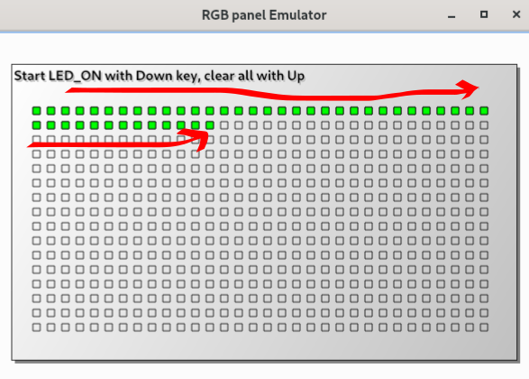
or so:
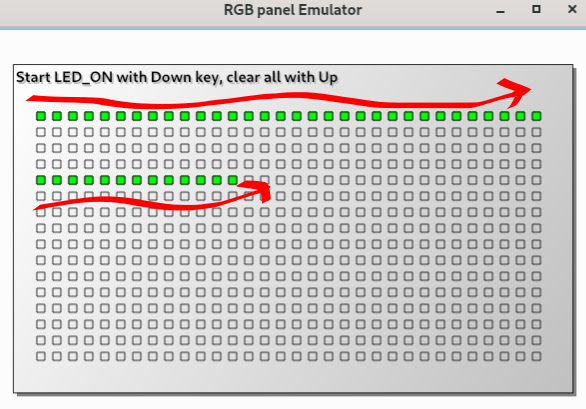
However, most scan4 matrices are arranged differently. Most often, I came across those where the leds are organized into chains of 8 pieces and are lit alternately on one row, then on the other. The order of these sets of 8 diodes can be different, as well as the direction of their bypass - from right to left or from left to right. But all of these options have something in common - that the leds do not light up along the entire length of the row, but alternately on different lines, like this:
(i got the image from this thread)
I want to show that if we initially consider such a scheme to be “normal”, the transformation of coordinates for different variants of such matrices will become quite simple.
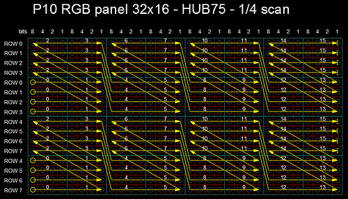
Let’s try to calculate the base address of a particular LED in the memory buffer. First of all, the data is displayed on the panel by scans. This means that the buffer will first contain all the points of the first scan, then the second, then the third… Determining which scan a particular diode belongs to is not difficult. From the picture above, we see that scan0 data is displayed in rows 0 and 4 of the matrix, scan1 - in rows 1 and 5… If we define the number of scans for defined panel as nScans, the scan number of the corresponding diode will be determined as
y % nScans
and scan offset as
(y % nScans) * WIDTH *2 (1)
Inside the data of its scan, the point offset before starting of 8 led chain will be equal to
(x/8) * 16 (2)
Both expressions 1 and 2 are not influensed by the organization of the last 8 led chains.
Now consider options for how these chains can be organized.
First, leds can be starts from upper of two rows or from lower - let’s denote this as Upper and Low. Second, the pixels in the upper row can go from left to right (in the Positive direction) or from right to left (Negative). And the third part of the variety - the diodes in the second row can go in the Same direction as in the first or towards the opposite(Different).
These three factors give us 8 variants for 4scan matrices, which I will denote for example U-P-S - the Upper-Negative-Same.
The following is just code. The general coordinate transformation for all types of 4scan matrices can be written as
 // set Upper/Low  Positive/Negative and Same/Different options
    bool tUpper = true;
    bool tPos = false;
    bool tSame = false;
    uint y_shift = 0;

    uint half_of_height = HEIGHT/2;

    // because we have two sets of RGB pins for upper and low part
    // of matrix, we need to calculate only for half of panel
    if (y >= half_of_height) {
        y_shift = half_of_height;
        y = y - half_of_height;
    }
    // offset of the last 8 leds
    // according to expessions 1 and 2 from the text above
    uint base_addr = (y % nScans) * WIDTH *2 + (x / 8) * 2 * 8;

    // first 8 leds can be Upper or Low row
    if (!((y / nScans) ^ tUpper)) base_addr += 8;

    // leds direction from left to right or opposite - 1st row
    if (y / nScans == 0) {
        if (tPos) base_addr += x % 8;
        else base_addr += (7 - x % 8);
       }
       // and 2nd row
    else {
        if (!(tPos ^ tSame)) base_addr += x % 8;
        else base_addr += (7 - x % 8);
    }

    // return to the panel limits
    y = base_addr/WIDTH;
    x = base_addr % WIDTH;
    y = y + y_shift;
  // Done!
PS This way of handling 4scan panels is used in my library DMD_STM32.
Based the general principle, you can add code for new variants of matrices, even without having them in your hands, only according to the test video, for example.