I have an ESP32 setup that I’ve been using for awhile using the latched approach. (RGB and ADDR are multiplexed). I got a new batch of LED displays that I notice are FM6126B based. They actually worked right from the get-go, but they are much dimmer than the other displays I was using. (I’m uncertain what those displays are based on because I don’t see numbers that I recognize from any of the various websites. They have SM5166P & J?5020GP chips.) I tried adding the FM6126B init routines and they do show “init” on the screen, but I get the same dim display. BTW, the colors also seem a little off from what I suspect…
I did confirm that the same code works on the old displays, so I’ve mostly isolated it to the display. I’m just wondering if there are configuration changes I can make that will brighten the display up. I think those FM6126 chips have configuration registers, I just don’t know how to set them up with the SmartMatrix code.
This is the first I’ve heard of the FM6126B (vs FM6126A), and all I can find is a datasheet in Chinese which is of only limited use. If it doesn’t have the same initialization sequence as the FM6126A, someone will have to reverse engineer it in order to add support for it to SmartMatrix Library, and I don’t have a sample panel or the time to do it myself unfortunately.
I found my way to the configuration register and tried playing with the values that you’re sending (0x7FFF for C12 and 0x0040 for C13). I didn’t notice any change in the display output… I did this in both the MatrixEsp32Hub75Refresh_Impl.h and the MatrixEsp32Hub75Refresh_NT_Impl.h file (because I can’t figure out which one is actually being used ).
What else would you do to debug a display board that was unusually dark, but otherwise working?
Now I’m concerned the ESP32 levelshifting buffers (and RGB/ADDR demux) may be interfering with being able to clock the shift registers while the latch is high.
To your question, Yes, confirmed that I added that option. I’ve been playing with the code that sends the configuration number and using Serial.printf’s to verify it’s functioning. So far, my main hypothesis is that the chips aren’t actually getting programmed. But also, I don’t see the blocks of LEDs simply not working that others report. I just see a very dim display.
I’ve tried various approaches: changing the values being sent to ones that should just turn off the display. No change. Changing the clocking of the Latch signal. (the data sheet says its latched on the 0->1 transition) Changing the extra clock signals to occur after all PIXELS_PER_LATCH shifts have occured. None of these create any change.
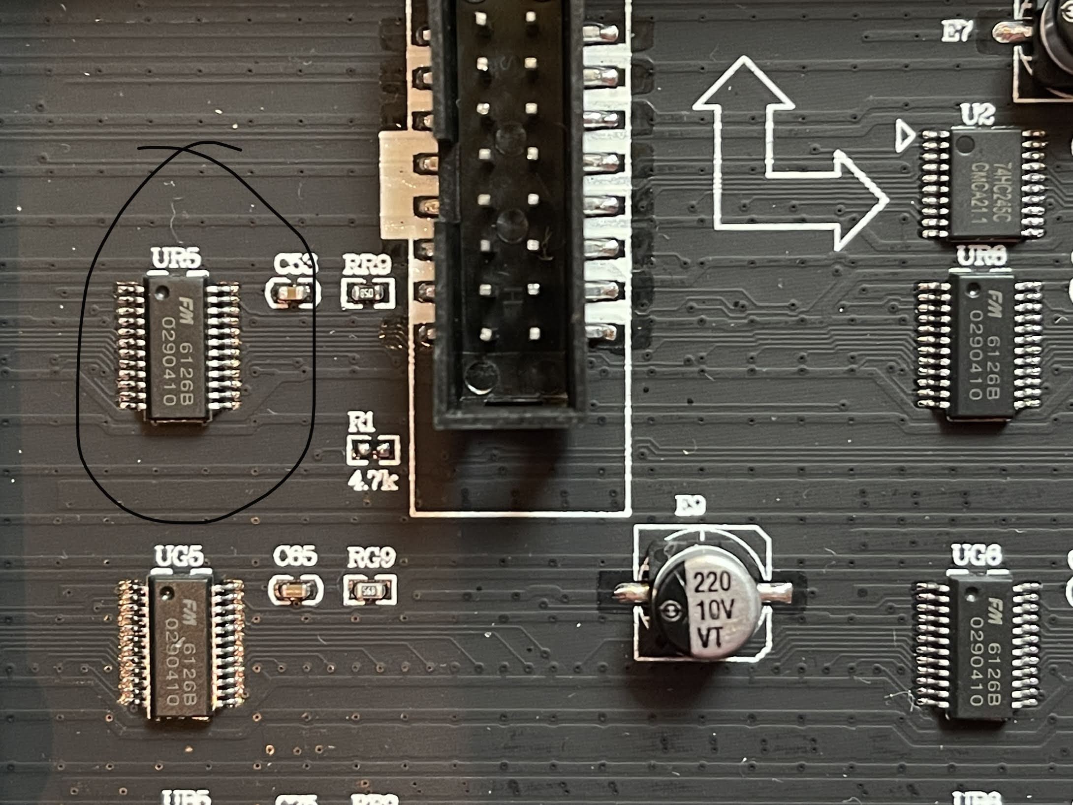
My board uses the latched buffers we were working on with an early ESP32 board. (Pin definition below.)
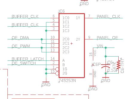
Looking at the x253 data selector, the BUFFER_CLOCK is selected only when BUFFER_LATCH is low. Whenever it’s high, PANEL_CLK is grounded. Thus, it doesn’t seem like you can clock the data when the latch is held high. I know it’s been awhile, but am I reading that correctly?
That was it! I lifted pins 3 and 5 and tied them to pins 4 and 6 of the data selector. The display is bright and working now, meaning the shift register config register of the FM6126 was just not getting programmed until I could toggle the clock while the latch was high.
One problem remains: the last vertical column of the display looks like it might be showing address lines. I’m not entirely convinced the whole display isn’t just shifted left by one pixel… but I can’t verify that yet… I suspect you had that selector there for a reason, I just don’t know what it is yet.
Another question: is there already a way to swap Blue and Green? It appears the color order on this annoying panel is also wonky. I can’t just redefine the pins because the address lines would move as well…
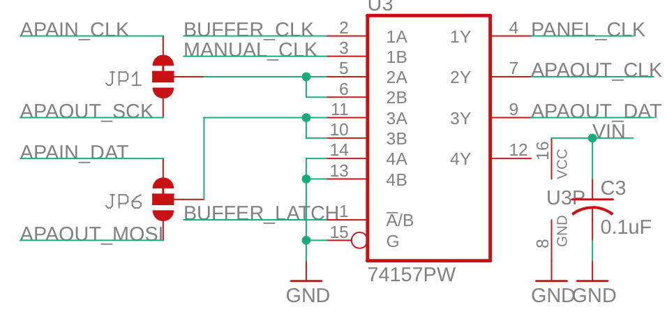
According to my notes here I tested the FM6126A code on an ESP32 circuit with a latch. Now I remember that on recent boards - not yet published, sorry - in anticipation of supporting panels like this I added a manual CLK pin that can be toggled while the latch pin is high and otherwise blocking the normal CLK pin.
You can find this mentioned in the code #ifdef CLK_MANUAL_PIN
You’ll need to add this pin and attach it to pins 3 and 5 on your circuit, and that will fix the shifted columns/address column issue you’re seeing.
I’m glad you pushed through and found a fix. I updated the wiki to help the next person with this situation, and to help with my memory as I didn’t remember that there were complications with the latch.
There’s an easy way to swap colors in the Teensy Hardware config files, but I haven’t implemented this on ESP32 yet:
For ESP32 you’ll want to manually changes these lines in the library to swap the colors. Keep in mind that this code block is repeated twice, in loadMatrixBuffers24() and loadMatrixBuffers48() and you’ll want to change both, or maybe just the one you’re using for your project.
Does MANUAL_CLK need to go to both 3 and 5? Is OE_SWITCH used in normal operations to select between OE_DMA and OE_PWM?
Alternately, is it possible to solve the clock problem with an adjustment in timing? The address lines are being clocked into a shift register… but it’s actually BUFFER_LATCH that clocks the address lines onto the PANEL_ADX lines. What signal gates those address lines onto the panel itself? (It seems like those address lines will be quite mucked up during the actual clocking of data into the configuration registers… and yet the panel mostly looks good.)
The color swap worked perfectly. I just used the already existing option, though maybe not everyone with an FM6126B will need a color swap…
                    if(optionFlags & SMARTMATRIX_OPTIONS_FM6126A_RESET_AT_START) {
		    // SWAP Blue and Green just before sending out the data
		    if (tempRow0[i+k].red & mask)
			v|=BIT_R1;
		    if (tempRow0[i+k].green & mask)
			v|=BIT_B1;
		    if (tempRow0[i+k].blue & mask)
			v|=BIT_G1;
		    if (tempRow1[i+k].red & mask)
			v|=BIT_R2;
		    if (tempRow1[i+k].green & mask)
			v|=BIT_B2;
		    if (tempRow1[i+k].blue & mask)
			v|=BIT_G2;
	    } else {
		    if (tempRow0[i+k].red & mask)
			v|=BIT_R1;
		    if (tempRow0[i+k].green & mask)
			v|=BIT_G1;
		    if (tempRow0[i+k].blue & mask)
			v|=BIT_B1;
		    if (tempRow1[i+k].red & mask)
			v|=BIT_R2;
		    if (tempRow1[i+k].green & mask)
			v|=BIT_G2;
		    if (tempRow1[i+k].blue & mask)
			v|=BIT_B2;
	    }
It just needs to go to 5 (I think, I don’t have time or energy to verify). OE_SWITCH is for a feature that was never implemented and should be fixed at a zero level.
On the ESP32, the clock is toggled any time GPIO is updated by DMA, and LATCH is toggled by DMA, so clock will toggle too. The MUX gating LATCH is a way to keep an extra bit (or extra bits) of data from being shifted out while latch is toggled.
The address lines are being clocked into a shift register
With most panels, the address lines are latched into a latch or flip flop on the panel, not a shift register. For the modes that SmartMatrix Library exercises on the FM6126A/B, I think it’s acting as a latch, not a shift register.
Worked! I hooked up GPIO 16 to the unused inputs on the MUX that is selected when LATCH is high. And GPIO 16 is now assigned to MANUAL_CLK_PIN. I made a minor change to the MANUAL_CLK_PIN code so that’s it’s set back to 0 when the actual clock is set back to 0 (so it gets the advantage of the delay(1)). Now everything lights up perfectly and the display is bright - maybe even brighter than the non-FM6126B based board.
Except for the lack of documentation, I really like that configuration register in the FM6126. It would be nice if it came out of reset in a configuration that made it more closely emulate the other chips… but that may be the difference between the A and B versions. Too bad there isn’t good docs!!
Here’s the modified clock logic code from Refresh_Impl.h:
Side question: in a nutshell, is it possible to lower the DMA memory footprint of SmartMatrix similar to ESP32-HUB75-MatrixPanel-I2S-DMA? So far, I know his iteration on your code doesn’t support the multiplexed ADDR/RGB data. I haven’t dug into the bowels of both yet, but plan to… as is, when I drive a 128x64, I’m down to “lsbMsbTransitionBit of 7” …
No, ESP32-HUB75-MatrixPanel-I2S-DMA is designed to be very memory efficient, where SmartMatrix Library is designed to support high quality graphics at the cost of high memory usage. My current plan to make SmartMatrix Library work with memory constrained CPUs is to use a second ESP32 to offload the double buffering storage and matrix refresh:
I have this working with WLED (if you’re not familiar, it’s already close to maxing out the capabilities of an ESP32, so there’s no room for HUB75 refresh on top of it). It’s only supporting 64x64 right now, but the basic Pixelvation Engine circuit doesn’t have the latch, and with the latch it should support 128x64.
I know you’re going in a different direction, but I thought I’d update you on my progress. I got ESP32-HUB75-MatrixPanel-I2S-DMA working with your latch circuitry. This means it’s driving a 64x64 display with 23kB of DMA memory. Overall heap usage of 26944 bytes. I’ve had it driving 8 panels at about 132k of usage (at a paltry 9 fps on the Plasma demo, so…).
I have it forked here in case anyone is looking for something like this. I need it in order to have a better chance of running the WiFiClientSecure library while using a 128x64 screen. I do miss the features of the SmartMatrix library though!
Hi twinotter,
Would you please post full version of codes and libs, and the wiring between esp32 and FM6126B based led matrix panel?
I’ll appreciate it!
 ).
).