Hello everyone,
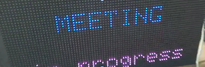
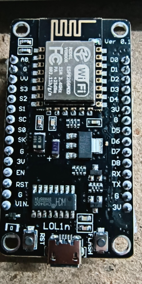
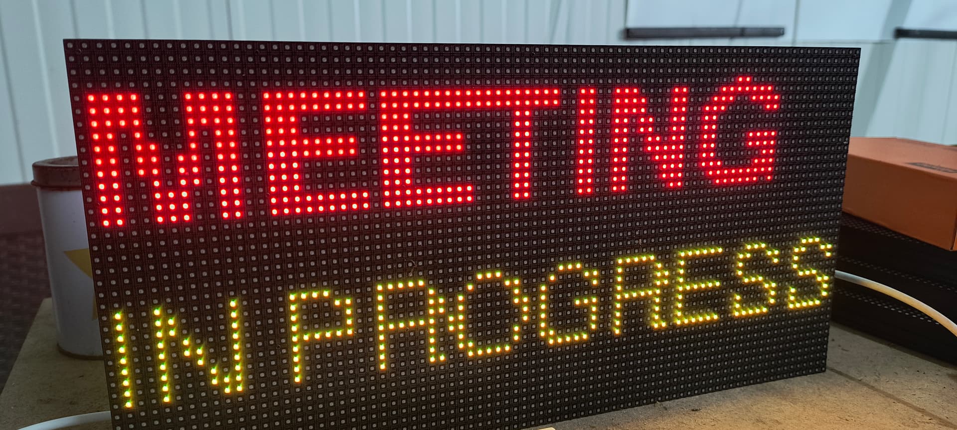
I am working on a small project using an ESP8266 and a P4 LED matrix panel (80×40 pixels, 1/20 scan). My goal is to display a static message (no scrolling or animations), for example “MEETING” on the top line and “in progress” below it.
I am currently using the PxMatrix library and Adafruit GFX fonts (e.g. FreeSansBold12pt7b) to get a clear and readable result. The panel works, but I would appreciate help with correct wiring (pin connections, scan type considerations) and best practices in the code to ensure stable refresh, no flickering, and proper font rendering on a 1/20 scan panel.
If anyone has experience with ESP8266 + P4 (80×40) panels, especially regarding wiring or configuration details, your guidance would be very helpful. Thank you in advance.
#include <ESP8266WiFi.h>
#include <Ticker.h>
#include <PxMatrix.h>
Ticker display_ticker;
#define P_LAT 16
#define P_A 5
#define P_B 4
#define P_C 15
#define P_D 12
#define P_OE 2

PxMATRIX display(80, 40, P_LAT, P_OE, P_A, P_B, P_C, P_D);
uint8_t display_draw_time = 30;
void display_updater() {
display.display(display_draw_time);
}
void setup() {
WiFi.mode(WIFI_OFF);
WiFi.forceSleepBegin();
delay(1);
display.begin(16);
display_ticker.attach(0.002, display_updater);
display.fillScreen(display.color565(0, 0, 0));
display.setTextWrap(false);
display.setTextColor(display.color565(255, 0, 0));
display.setTextSize(1);
display.setCursor(18, 8);
display.print(“MEETING”);
display.setTextColor(display.color565(0, 255, 255));
display.setCursor(5, 23);
display.print(“in progress”);
}
void loop() { }
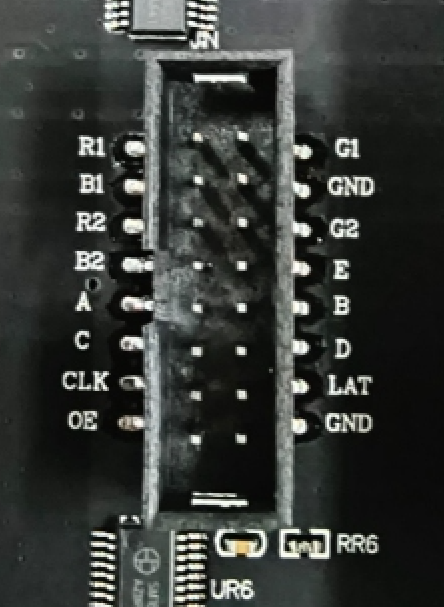
R1 → D7
G1 → R2
B1 → G2
R2 → R1
G2 → G1
B2 → B1
E → D3
A → D1
B → D2
C → D8
D → D6
CLK → D5
LAT → D0
OE → D4
GND → GND