Pixel mapping known, but can’t get correct picture.
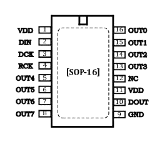
I think problem is in DP32020A, which have different control inputs from commonly used 138 decoders. It uses serial interface - DIN, DCK, RCK, DOUT (data, clock, output register latch, data for next chip), instead of A0, A1 and A2 for decoder-multiplexers.
DP32020A - is shift register, therefore it needs different control. Whether SmartMatrix library supports such type ICs in role of decoder.
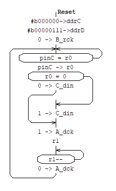
I used ATMEGA88 microcontroller to convert “A”, “B”, “C”, “D” address signals to DIN (on C line) and DCK (on A line) signals for 32020 chip.
ATMEGA88 runs on an internal RC oscillator, so no external components are required.
A very simple code was sufficient for this purpose. On port C, which is configured as input, we read “A”, “B”, “C”, “D” address. “C_din” and “A_dck” are pins of D port configured as output. “B_rck” is not used and always in zero state.
Although it is quite possible to use an Arduino nano.
Wow, what a great idea! I never considered implementing address translation with a little micro. I’ll add this solution to the wiki when I have time to let others know SmartMatrix library can (with a little help) work with more types of panels
Hi
Work with shift register multiplexer is a very simple, the code is literally a couple the lines:
        digitalWrite(pin_DMD_B, HIGH);
		digitalWrite(pin_DMD_C, (curr_row == 0)); // Shift out 1 for line 0, 0 otherwise
		digitalWrite(pin_DMD_A, HIGH); // Clock out this bit
		digitalWrite(pin_DMD_A, LOW);
		digitalWrite(pin_DMD_B, LOW);
The code - put 1 in the register at row 0 and shift it one bit at every next row.