/*
- P10 Panel Test - Display Numbers 1-12
- For 2x6 P10 panels (32x16 each)
*/
#include <Adafruit_GFX.h>
#include “ESP32-HUB75-MatrixPanel-I2S-DMA.h”
#include “ESP32-VirtualMatrixPanel-I2S-DMA.h”
#include “Fonts/Font9x14.h”
// Define custom class derived from VirtualMatrixPanel
class CustomPxBasePanel : public VirtualMatrixPanel
{
public:
using VirtualMatrixPanel::VirtualMatrixPanel; // inherit VirtualMatrixPanel’s constructor(s)
protected:
VirtualCoords getCoords(int16_t x, int16_t y); // custom getCoords() method for specific pixel mapping
};
// custom getCoords() method for specific pixel mapping
inline VirtualCoords CustomPxBasePanel ::getCoords(int16_t x, int16_t y) {
coords = VirtualMatrixPanel::getCoords(x, y); // call base class method to update coords for chaining approach
if ( coords.x == -1 || coords.y == -1 ) { // Co-ordinates go from 0 to X-1 remember! width() and height() are out of range!
return coords;
}
uint8_t pxbase = panelResX; // pixel base
// mapper for panels with 32 pixs height (64x32 or 32x32)
if (panelResY == 32)
{
if ((coords.y & 8) == 0)
{
coords.x += ((coords.x / pxbase) + 1) * pxbase; // 1st, 3rd ‘block’ of 8 rows of pixels
}
else
{
coords.x += (coords.x / pxbase) * pxbase; // 2nd, 4th ‘block’ of 8 rows of pixels
}
coords.y = (coords.y >> 4) * 8 + (coords.y & 0b00000111);
}
// mapper for panels with 16 pixs height (32x16 1/4)
else if (panelResY == 16)
{
if ((coords.y & 4) == 0)
{
// 1. Normal line, from left to right
coords.x += ((coords.x / pxbase) + 1) * pxbase; // 1st, 3rd ‘block’ of 4 rows of pixels
//2. in case the line filled from right to left, use this (and comment 1st)
//coords.x = ((coords.x / pxbase) + 1) * 2 * pxbase - (coords.x % pxbase) - 1;
}
else
{
coords.x += (coords.x / pxbase) * pxbase; // 2nd, 4th ‘block’ of 4 rows of pixels
}
coords.y = (coords.y >> 3) * 4 + (coords.y & 0b00000011);
}
return coords;
}
// ================= P10 MATRIX CONFIGURATION =================
#define R1_PIN 4
#define G1_PIN 16
#define B1_PIN 17
#define R2_PIN 21
#define G2_PIN 25
#define B2_PIN 26
#define A_PIN 19
#define B_PIN 23
#define C_PIN 18
#define D_PIN -1
#define E_PIN -1
#define LAT_PIN 22
#define OE_PIN 2
#define CLK_PIN 14
// Panel configuration
#define PANEL_RES_X 32 // P10 width
#define PANEL_RES_Y 16 // P10 height
#define NUM_ROWS 2 // 2 rows of panels
#define NUM_COLS 6 // 6 columns of panels
#define PANEL_CHAIN_LEN NUM_ROWS*NUM_COLS
#define VIRTUAL_MATRIX_CHAIN_TYPE CHAIN_TOP_RIGHT_DOWN
#define SERPENT true
#define TOPTDOWN true
// ================= GLOBAL OBJECTS =================
MatrixPanel_I2S_DMA *dma_display = nullptr;
CustomPxBasePanel *FourScanPanel = nullptr;
// ================= DISPLAY VARIABLES =================
uint16_t myRED, myGREEN, myBLUE, myYELLOW, myWHITE, myBLACK;
void setup() {
Serial.begin(115200);
delay(1000);
Serial.println(“\n\n========================================”);
Serial.println(“P10 Panel Test - Numbers 1-12”);
Serial.println(“2x6 P10 Panels (32x16 each)”);
Serial.println(“========================================”);
// Initialize display
Serial.println(“Initializing display…”);
HUB75_I2S_CFG mxconfig(
PANEL_RES_X * 2, // DO NOT CHANGE THIS
PANEL_RES_Y / 2, // DO NOT CHANGE THIS
NUM_ROWS * NUM_COLS // DO NOT CHANGE THIS
);
// Set pin assignments
mxconfig.gpio.r1 = R1_PIN;
mxconfig.gpio.g1 = G1_PIN;
mxconfig.gpio.b1 = B1_PIN;
mxconfig.gpio.r2 = R2_PIN;
mxconfig.gpio.g2 = G2_PIN;
mxconfig.gpio.b2 = B2_PIN;
mxconfig.gpio.a = A_PIN;
mxconfig.gpio.b = B_PIN;
mxconfig.gpio.c = C_PIN;
mxconfig.gpio.d = D_PIN;
mxconfig.gpio.e = E_PIN;
mxconfig.gpio.lat = LAT_PIN;
mxconfig.gpio.oe = OE_PIN;
mxconfig.gpio.clk = CLK_PIN;
// P10 specific settings
mxconfig.driver = HUB75_I2S_CFG::FM6124;
mxconfig.i2sspeed = HUB75_I2S_CFG::HZ_10M;
mxconfig.clkphase = false;
mxconfig.latch_blanking = 4;
mxconfig.min_refresh_rate = 150;
dma_display = new MatrixPanel_I2S_DMA(mxconfig);
if (!dma_display->begin()) {
Serial.println(“Display init failed!”);
while(1);
}
dma_display->setBrightness8(128);
dma_display->clearScreen();
delay(100);
// Create virtual display - TRY DIFFERENT CHAIN TYPES HERE
// Start with CHAIN_TOP_LEFT_DOWN (most common)
FourScanPanel = new CustomPxBasePanel(
(*dma_display),
NUM_ROWS, // 2 rows
NUM_COLS, // 6 columns
PANEL_RES_X, // 32 width per panel
PANEL_RES_Y, // 16 height per panel
VIRTUAL_MATRIX_CHAIN_TYPE // Try this first
// Other options:
// CHAIN_TOP_RIGHT_DOWN
// CHAIN_BOTTOM_LEFT_UP
// CHAIN_BOTTOM_RIGHT_UP
);
// Try different scan rates for P10
// FourScanPanel->setPhysicalPanelScanRate(FOUR_SCAN_16PX_HIGH);
// FourScanPanel->setPhysicalPanelScanRate(FOUR_SCAN_32PX_HIGH);
// Initialize colors
myRED = dma_display->color565(255, 0, 0);
myGREEN = dma_display->color565(0, 255, 0);
myBLUE = dma_display->color565(0, 0, 255);
myYELLOW = dma_display->color565(255, 255, 0);
myWHITE = dma_display->color565(255, 255, 255);
myBLACK = dma_display->color565(0, 0, 0);
Serial.println(“\nDisplay initialized successfully!”);
Serial.println("Virtual Display Size: " + String(FourScanPanel->width()) + “x” + String(FourScanPanel->height()));
// Run test patterns
testAllPanels();
testPanelNumbers();
}
void testAllPanels() {
Serial.println(“\n=== TEST 1: Fill each panel with different colors ===”);
uint16_t colors = {myRED, myGREEN, myBLUE, myYELLOW, myWHITE};
for(int row = 0; row < NUM_ROWS; row++) {
for(int col = 0; col < NUM_COLS; col++) {
int panelNum = row * NUM_COLS + col + 1;
int startX = col * PANEL_RES_X;
int startY = row * PANEL_RES_Y;
  // Fill panel with color
  FourScanPanel->fillRect(startX, startY, PANEL_RES_X, PANEL_RES_Y, colors[panelNum % 5]);

  Serial.print("Panel ");
  Serial.print(panelNum);
  Serial.print(" filled at (");
  Serial.print(startX);
  Serial.print(",");
  Serial.print(startY);
  Serial.println(")");

  delay(1000);
}
}
delay(2000);
FourScanPanel->fillScreen(myBLACK);
}
void testPanelNumbers() {
Serial.println(“\n=== TEST 2: Display panel numbers 1-12 ===”);
FourScanPanel->fillScreen(myBLACK);
// Set font
FourScanPanel->setFont(&Font9x14);
FourScanPanel->setTextColor(myWHITE);
for(int row = 0; row < NUM_ROWS; row++) {
for(int col = 0; col < NUM_COLS; col++) {
int panelNum = row * NUM_COLS + col + 1;
int panelCenterX = col * PANEL_RES_X + (PANEL_RES_X / 2) - 4;
int panelCenterY = row * PANEL_RES_Y + (PANEL_RES_Y / 2) + 4;
  FourScanPanel->setCursor(panelCenterX, panelCenterY);
  FourScanPanel->print(panelNum);

  Serial.print("Panel ");
  Serial.print(panelNum);
  Serial.print(" number at (");
  Serial.print(panelCenterX);
  Serial.print(",");
  Serial.print(panelCenterY);
  Serial.println(")");
}
}
// Also draw borders for reference
FourScanPanel->setTextColor(myRED);
FourScanPanel->setCursor(1, 1);
FourScanPanel->print(“TEST”);
// Draw red border around entire display
for(int x = 0; x < FourScanPanel->width(); x++) {
FourScanPanel->drawPixel(x, 0, myRED);
FourScanPanel->drawPixel(x, FourScanPanel->height() - 1, myRED);
}
for(int y = 0; y < FourScanPanel->height(); y++) {
FourScanPanel->drawPixel(0, y, myRED);
FourScanPanel->drawPixel(FourScanPanel->width() - 1, y, myRED);
}
Serial.println(“\nNumbers displayed. Check if panels show 1-12 in order.”);
Serial.println(“If numbers are out of order, change CHAIN_TYPE in code.”);
}
void loop() {
// Flash the numbers
static unsigned long lastChange = 0;
static bool showNumbers = true;
if(millis() - lastChange > 2000) {
lastChange = millis();
showNumbers = !showNumbers;
if(showNumbers) {
  testPanelNumbers();
} else {
  FourScanPanel->fillScreen(myBLACK);
  FourScanPanel->setTextColor(myGREEN);
  FourScanPanel->setFont(&Font9x14);
  FourScanPanel->setCursor(60, 14);
  FourScanPanel->print("2x6 P10");
}
}
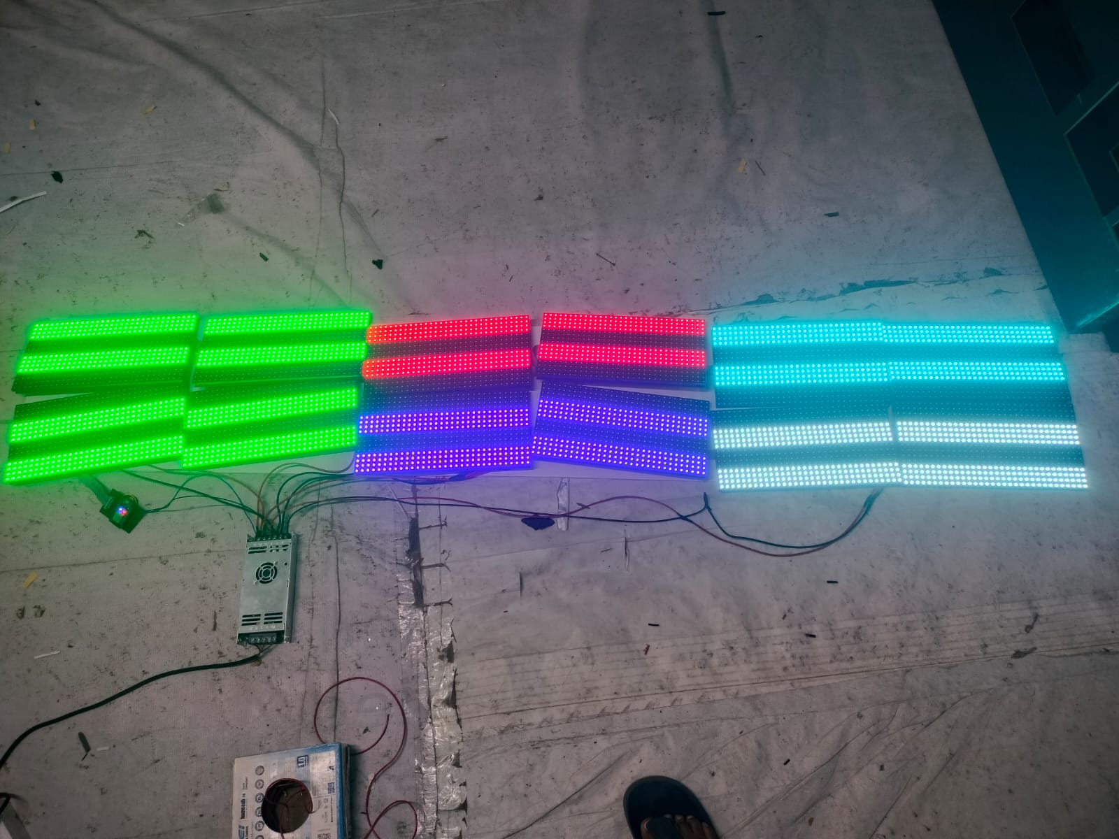
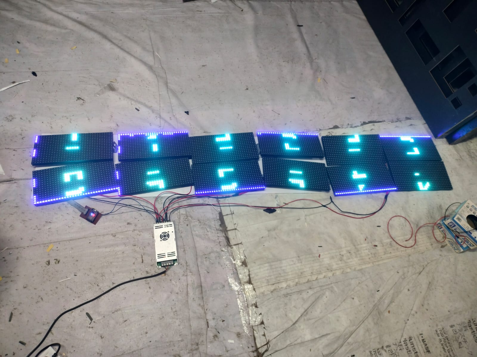
} Output showing in 1st row : 1st and 3rd 4 row glowing and in 2Row : 2nd and 4th 4 Row glowing. Help me out with it