I have a HUB75 P10 Panel, Teensy 3.2, Smart Matrix Shield V4.
The plan is to create a 32x32 panel but currently when running the demos the images are scrambled so I have changed the setup to a single 16x32 panel for the time being to understand the problem.
I am running the latest Smart Matrix library installed from the arduino library manager.
I am attempting to use the MultiRowRefreshMapping Sketch.
The comment at the beginning:
e.g. each RGB channel on a HUB75 P10 32x16 /2 panel fills pixels across four rows at once, and in a non-linear order.
Seems relevant to what I am seeing. When running the Mode Map Reverse Engineering or the Mode MAP Testing I address 4 red Pixels at a time when the description suggests that it should be 1 at a time. I can’t seem to find a state when I don’t write to 4 rows at a time with the Red Colour. I think I can work out the order of the mapping once I solve the reason I’m writing 4 rows at a time and not a single pixel as expected. I can upload videos etc but I’m hoping a nudge in the right direction will be all that is required. If a nudge helps I’ll update this post with how I got it working. Thanks in advance.
You might have the wrong panel type selected in the sketch, can you paste your code? Can you upload an image of the back of the panel with any model number clearly shown?
You might not have enough pixels set in kMatrixWidth, so you’re not filling your panel with pixels. If you filled your panel with 1/4 of the pixels it needed, then it would take 4 refreshes to fill your panel, and the pixels would be repeated 4 times
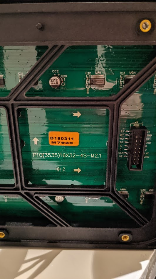
From the back of the panel I have assumed it is a 1/4Scan (MOD4) panel.
So based on that and following your comments in the sketch I applied these settings:
#if (SKETCH_MODE == MODE_MAP_REVERSE_ENGINEERING)
const uint16_t kMatrixWidth = 64; // must be multiple of 8
const uint16_t kMatrixHeight = 8;
//const uint8_t kPanelType = SM_PANELTYPE_HUB75_4ROW_MOD2SCAN; // Use this to reverse engineer mapping for a MOD2 panel
const uint8_t kPanelType = SM_PANELTYPE_HUB75_8ROW_MOD4SCAN; // Use this to reverse engineer mapping for a MOD4 panel #endif
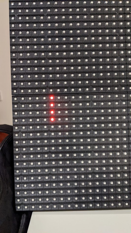
When I run this. Instead a single pixel. Its 4 rows of pixels as shown here (please note this image shows a second panel stacked on top that is currently not wired in):
I have noted that the HUB75 connector on these panels is ABCD but as yet have not found the weather this should be a problem or not from reading through the forum posts.
Well at least its not just me! There is definitely something odd. I’m experimenting with trying to draw a single pixel. So far I always draw a line of 4. Starting to wonder if the problem is hardware related. I have a second teensy and shield somewhere I might see if I get any different results with that.
The mod4 panels I’ve used drive rows spaced four rows apart at the same time, so when running the TEST mode in MultiRowRefreshMapping you’d expect to see red pixels on row 0 and row 4 during the first pass.
I tried new hardware. Same result. So looking more into the panels.
I managed to read of the IC’s on the back of the panel. Not to easy because its lacquered.
Its a DP5020B - 8C3102. I bought these panels some years ago.
There are also a pair of 74HC245C’s on each panel.
I ran the Mode Map Testing Sketch with settings:
const uint16_t kMatrixWidth = 32; // must be multiple of 8
const uint16_t kMatrixHeight = 16;
const uint8_t kPanelType = SM_PANELTYPE_HUB75_16ROW_32COL_MOD4SCAN;
And here is the result:
I’m going to try and make a datasheet comparison between the DP5020B and the DP5220X but any help would be much appreciated. The other thing I noticed is the labeling on my panel I have ABCD but I have GND where ones on the WIKI page have E.
I have two Smart Matrix V4 Shields both give the same result. I only have these panels so no I have not tested with other panels. Maybe I am doing something silly with the hardware wiring I will double check but Its a simple Ribbon cable going from Shield to Panel.
This is the code that accompanies the video shown above.
// uncomment one line to select your MatrixHardware configuration - configuration header needs to be included before <SmartMatrix.h>
#include <MatrixHardware_Teensy3_ShieldV4.h>        // SmartLED Shield for Teensy 3 (V4)
//#include <MatrixHardware_Teensy4_ShieldV5.h>        // SmartLED Shield for Teensy 4 (V5)
//#include <MatrixHardware_Teensy3_ShieldV1toV3.h>    // SmartMatrix Shield for Teensy 3 V1-V3
//#include <MatrixHardware_Teensy4_ShieldV4Adapter.h> // Teensy 4 Adapter attached to SmartLED Shield for Teensy 3 (V4)
//#include <MatrixHardware_ESP32_V0.h>                // This file contains multiple ESP32 hardware configurations, edit the file to define GPIOPINOUT (or add #define GPIOPINOUT with a hardcoded number before this #include)
//#include "MatrixHardware_Custom.h"                  // Copy an existing MatrixHardware file to your Sketch directory, rename, customize, and you can include it like this
#include <SmartMatrix.h>

#define MODE_MAP_REVERSE_ENGINEERING  0
#define MODE_MAP_TESTING              1

//#define SKETCH_MODE   MODE_MAP_REVERSE_ENGINEERING
#define SKETCH_MODE   MODE_MAP_TESTING

#define COLOR_DEPTH 24                  // leave this as 24 for this sketch

#if (SKETCH_MODE == MODE_MAP_REVERSE_ENGINEERING)
const uint16_t kMatrixWidth = 128;        // must be multiple of 8
const uint16_t kMatrixHeight = 4;
const uint8_t kPanelType = SM_PANELTYPE_HUB75_4ROW_MOD2SCAN;    // Use this to reverse engineer mapping for a MOD2 panel
//const uint8_t kPanelType = SM_PANELTYPE_HUB75_8ROW_MOD4SCAN;  // Use this to reverse engineer mapping for a MOD4 panel
#endif

#if (SKETCH_MODE == MODE_MAP_TESTING)
const uint16_t kMatrixWidth = 32;        // must be multiple of 8
const uint16_t kMatrixHeight = 16;
const uint8_t kPanelType = SM_PANELTYPE_HUB75_16ROW_32COL_MOD4SCAN;   // use SM_PANELTYPE_HUB75_16ROW_MOD8SCAN for common 16x32 panels
#endif

const uint8_t kRefreshDepth = 36;       // leave as 36 for this sketch
const uint8_t kDmaBufferRows = 4;       // known working: 2-4, use 2 to save memory, more to keep from dropping frames and automatically lowering refresh rate
const uint32_t kMatrixOptions = (SM_HUB75_OPTIONS_NONE);      // see http://docs.pixelmatix.com/SmartMatrix for options
const uint8_t kBackgroundLayerOptions = (SM_BACKGROUND_OPTIONS_NONE);

SMARTMATRIX_ALLOCATE_BUFFERS(matrix, kMatrixWidth, kMatrixHeight, kRefreshDepth, kDmaBufferRows, kPanelType, kMatrixOptions);
SMARTMATRIX_ALLOCATE_BACKGROUND_LAYER(backgroundLayer, kMatrixWidth, kMatrixHeight, COLOR_DEPTH, kBackgroundLayerOptions);

void setup() {
  matrix.addLayer(&backgroundLayer);
  matrix.begin();

  matrix.setBrightness(128);

  // do a (normally unnecessary) swapBuffers call to work around ESP32 bug where first swap is ignored
  backgroundLayer.swapBuffers();
}

void loop() {
  for(int j=0; j<kMatrixHeight; j++) {
    rgb24 colorByHeight;

    colorByHeight.red = 0xff;
    if(j & 0x01)
      colorByHeight.green = 0xff;
    if(j & 0x02)
      colorByHeight.blue = 0xff;

    for(int i=0; i<kMatrixWidth; i++) {
      backgroundLayer.drawPixel(i,j,colorByHeight);
      backgroundLayer.swapBuffers();
      delay(250);

      backgroundLayer.fillScreen({0,0,0});
    }
  }
}
I had a look at the DP5020b datasheet. One thing that I noticed that I could be doing wrong is clock speed. I haven’t done anything to the library to modify this but it would seem quite key to get this right for the IC. The DP5020b says fclk should be 30MHz.
I don’t think my comments on Clock Speed were on the right track. The known to work DP5220 also states 30MHz has for fclk.
A bit of investigation:
I modified the code to just draw a single pixel.
So it seems if I try to write a single pixel on the first row of a column, I get a pixel on 4 rows in that column or an output of 1111.
If I try to write to a single pixel in a column on the second row of a column I get: nothing on row 1, but a pixel on rows 2,3 and 4 or an output of 0111.
For the 3 row the output is 1011.
For the 4th row the output is 0011.
It doesn’t matter what column I pick in the panel the sequence is the same.
Interestingly though trying to write BLUE colour to the first 8 rows does not work. But does for the second 8 rows.
It seems I need to adjust the data for the control of the rows the ABC addressing and it seems possible that something may be need to be swapped and perhaps the BLUE and the ABC addressing issue are linked.
Can anyone offer any advice of where I might look in the library to break down this problem further and where I might try to modify the library to suit the panel?
Hi, I’ve also had two of these panels for a few years now. They show the same. If they work for you I will be happy. I will finally be able to use them.
It’s not easy to try to decode what’s going on with the panel, or to try to suggest a fix. It almost seems like the address and RGB lines may be swapped, but I don’t think that’s quite right. I may come back to this later when I have more time, sorry I can’t be of much help right now
Hi Louis, I understand, I would like to help. I have seen something that might help. As i mentioned the panels I have have 2 74HC’s on them as well as the LED drivers. In your documentation it talks about some A and B only type panels using these shift registers:
“There are some high pixel density panels, e.g. 64x64 with 2.5mm pitch, that have only “A” and “B” address lines despite being specified as /32 scan (normally should have 5 address lines “A,B,C,D,E”). They use a shift register for updating the address, instead of directly driving the address lines. These panels are not compatible with the SmartMatrix or SmartLED Shields, or the SmartMatrix Library, and are unlikely to be supported anytime in the future.”
Is it possible that I have some sort of hybrid panel? If it is unusual to have a pair of 74HC’s on each panel please let me know and I will do some digging into how these panels have been made.
if you have not already figured it out it is 4s/ 1/4 scan panel i have a 32x16 panel with 8s or 1/8 working very well see my image posted on other post.one more thing try testing D Pin with multimeter in continuity mode I am sure it is GND pin.
Hello, I’m new to this community and to Smartmatrix. But not in coding and interfacing things that are not suppose to.
BTW I’m a french ingineer.
I have in stock a number of 16x32 4S matrix.
They are divided in two types :
_ The one that works perfectly using SMARTMATRIX_HUB75_16ROW_32COL_MOD4SCAN_V3 model
The ones that display a colmun of 4 or 3 pixels wtith MultiRowRefreshMapping test.
After sone further research on the second case, I found that A,B,C and D must be used this way
Line 0 : A=0, B=1, C=1, D=1,
Line 1 : A=1, B=0, C=1, D=1
Line 2 : A=1, B=1, C=0, D=1
Line 4 : A=1, B=1, C=1, D=0
use R1,G1,B1 for the 4 first lines (0 to 3)
use R2,G2,B2 for the 4 last lines (4 to 7)
Just have to implement this logic in Smartmatrix.
My regular Matrix use a ship : LEDASIC PR4538 to do this job on the card by decoding A and B signal and split then in 4 outputs (line select)
Hope this wil help you.
I Have a piece of code that run on a ESP32 to prove this algorithm.
Best regards
Eric
That’s a lot of changes that need to be made, and don’t fit with how other HUB75 panels work, so you’ll probably have to hack support in. You’ll find most of the code to change in this file:
Search for gpioRowAddress for where you’d need to modify the address to output your modified logic. Depending on the hardware and color depth you’re using you may only need to change some of those pieces of code.
If you need to swap R1 for R2, etc, look for code like this:
You might need to double the height of the panel so that you get enough calls to loadMatrixBuffers, as you’re only outputting one channel at a time.
In fact when I say ligne 0 it fill 2 physical lines , line 5 and then Line 0
I have to sned 64 pixels sequences, with the same A,B,C,D setting, to see 2 lines filled with a gap of 3 lines beetwin them
Its OK , my Patch works pretty Well.
Just a simple change in gpioRowAddress to A,B,C,D pins processing. and a new mapping; et voila!
Some gost pixels issue to solve latter.
And create a new option (cause now its inside #ifdefine (ERIC_PATCH)
Thanks for advices and your great software.
I looking for P10 16x32 1/8 panels If you know somes that works ant that can be connected using C-Shape Tyle.
Best regards
Eric
Panels that use MultiRowRefreshMapping won’t be able to use C shaped chaining. I don’t know of any P10 /8 panels. Why do you need C shaped over Z shaped?