New P2, 1/32 Scan, 64*64, Led panel with different IC chip controller

Dear Pinsball,

Thank you very much for your response. I am using STM32F103VET6 running at 72MHz, and I indeed added some NOPS() both between Clock high/low, and Latch high/low. Below is my piece of code, sorry I didn’t use macro definitions so it is kind of messy.

int main (void) {
  
  Bsp_Init();
  
  LL_APBx_EnableClock(GPIOD);
  LL_APBx_EnableClock(GPIOE);
  
  LL_GPIO_SetPinMode(GPIOC, LL_GPIO_PIN_6, LL_GPIO_MODE_OUTPUT);
  LL_GPIO_SetPinSpeed(GPIOC, LL_GPIO_PIN_6, LL_GPIO_SPEED_FREQ_HIGH);
  
  LL_GPIO_SetPinMode(GPIOD, LL_GPIO_PIN_0, LL_GPIO_MODE_OUTPUT);
  LL_GPIO_SetPinMode(GPIOD, LL_GPIO_PIN_1, LL_GPIO_MODE_OUTPUT);
  LL_GPIO_SetPinMode(GPIOD, LL_GPIO_PIN_2, LL_GPIO_MODE_OUTPUT);
  LL_GPIO_SetPinMode(GPIOD, LL_GPIO_PIN_3, LL_GPIO_MODE_OUTPUT);
  LL_GPIO_SetPinMode(GPIOD, LL_GPIO_PIN_4, LL_GPIO_MODE_OUTPUT);
  LL_GPIO_SetPinMode(GPIOD, LL_GPIO_PIN_5, LL_GPIO_MODE_OUTPUT);
  LL_GPIO_SetPinMode(GPIOD, LL_GPIO_PIN_6, LL_GPIO_MODE_OUTPUT);
  
  LL_GPIO_SetPinSpeed(GPIOD, LL_GPIO_PIN_0, LL_GPIO_SPEED_FREQ_HIGH);
  LL_GPIO_SetPinSpeed(GPIOD, LL_GPIO_PIN_1, LL_GPIO_SPEED_FREQ_HIGH);
  LL_GPIO_SetPinSpeed(GPIOD, LL_GPIO_PIN_2, LL_GPIO_SPEED_FREQ_HIGH);
  LL_GPIO_SetPinSpeed(GPIOD, LL_GPIO_PIN_3, LL_GPIO_SPEED_FREQ_HIGH);
  LL_GPIO_SetPinSpeed(GPIOD, LL_GPIO_PIN_4, LL_GPIO_SPEED_FREQ_HIGH);
  LL_GPIO_SetPinSpeed(GPIOD, LL_GPIO_PIN_5, LL_GPIO_SPEED_FREQ_HIGH);
  LL_GPIO_SetPinSpeed(GPIOD, LL_GPIO_PIN_6, LL_GPIO_SPEED_FREQ_HIGH);
  
  /*---------------------------*/
  
  LL_GPIO_SetPinMode(GPIOE, LL_GPIO_PIN_0, LL_GPIO_MODE_OUTPUT);
  LL_GPIO_SetPinMode(GPIOE, LL_GPIO_PIN_1, LL_GPIO_MODE_OUTPUT);
  LL_GPIO_SetPinMode(GPIOE, LL_GPIO_PIN_2, LL_GPIO_MODE_OUTPUT);
  LL_GPIO_SetPinMode(GPIOE, LL_GPIO_PIN_3, LL_GPIO_MODE_OUTPUT);
  LL_GPIO_SetPinMode(GPIOE, LL_GPIO_PIN_4, LL_GPIO_MODE_OUTPUT);
  LL_GPIO_SetPinMode(GPIOE, LL_GPIO_PIN_5, LL_GPIO_MODE_OUTPUT);
  
  LL_GPIO_SetPinSpeed(GPIOE, LL_GPIO_PIN_0, LL_GPIO_SPEED_FREQ_HIGH);
  LL_GPIO_SetPinSpeed(GPIOE, LL_GPIO_PIN_1, LL_GPIO_SPEED_FREQ_HIGH);
  LL_GPIO_SetPinSpeed(GPIOE, LL_GPIO_PIN_2, LL_GPIO_SPEED_FREQ_HIGH);
  LL_GPIO_SetPinSpeed(GPIOE, LL_GPIO_PIN_3, LL_GPIO_SPEED_FREQ_HIGH);
  LL_GPIO_SetPinSpeed(GPIOE, LL_GPIO_PIN_4, LL_GPIO_SPEED_FREQ_HIGH);
  LL_GPIO_SetPinSpeed(GPIOE, LL_GPIO_PIN_5, LL_GPIO_SPEED_FREQ_HIGH);
  
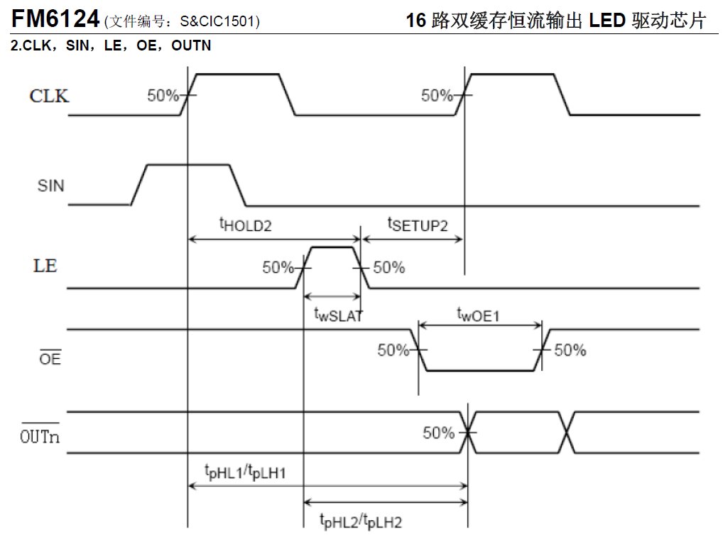
  GPIOC->BSRR |= (1 << 6);       /* OE-PIN Idle (High) */
  GPIOE->BRR  |= (1 << 5);       /* Latch Data (Low) */
  GPIOD->BRR  |= (1 << 6);       /* CK PIN (LOW) */
  
  __NOP();__NOP();__NOP();__NOP();__NOP();__NOP();__NOP();
  __NOP();__NOP();__NOP();__NOP();__NOP();__NOP();__NOP();
  __NOP();__NOP();__NOP();__NOP();__NOP();__NOP();__NOP();
  
  Bsp_LED_Off(BSP_LED0);
  
  SysTick->LOAD = 71999U;
  
  SysTick->CTRL |= SysTick_CTRL_TICKINT_Msk |
                   SysTick_CTRL_CLKSOURCE_Msk |
                   SysTick_CTRL_ENABLE_Msk;
                   
  GPIOC->BSRR = (1 << 6);        /* OE-High Disable Output */
	
  GPIOE->ODR &= (~(0x1F));       /* Select ROW 0 and ROW 15 */
  GPIOE->ODR |=  ((0x08));
  
	//Shift_Data64_Out(0xFF);
  //Shift_Data64_Out(0xFFFFFFFFFFFFFFFF);    /* Shift Data Out */
  //Shift_Data64_Out(0x5555555555555555);      /* Shift Data Out */
  Shift_Data64_Out(0x1111111111111111);      /* Shift Data Out */
  //Shift_Data64_Out(0x3F3F3F3F3F3F3F3F);      /* Shift Data Out */
  
	GPIOE->ODR  |= (1 << 5);        /* Latch Data - High Pulse */
  __NOP();__NOP();__NOP();__NOP();__NOP();__NOP();__NOP();
  __NOP();__NOP();__NOP();__NOP();__NOP();__NOP();__NOP();
		
  GPIOE->ODR  &= ~(1 << 5);
  __NOP();__NOP();__NOP();__NOP();__NOP();__NOP();__NOP();
  __NOP();__NOP();__NOP();__NOP();__NOP();__NOP();__NOP();
  
  GPIOC->BRR = (1 << 6);        /* Enable Output */


  while (1) {
    GPIOD->BRR = (1 << 6);
    __NOP();__NOP();__NOP();__NOP();__NOP();__NOP();
     
    GPIOD->BSRR = (1 << 6);
    __NOP();__NOP();__NOP();__NOP();__NOP();__NOP();
  }

}

Sorry, forgot to post the code of ‘Shift_Data64_Out’ function.

void Shift_Data64_Out(uint64_t data) {
  
  uint8_t i;
 
  for (i = 0; i < 64; i++) {
    
    if (data & (uint64_t)((uint64_t)(1) << (63 - i))) {
      GPIOD->BSRR = (1 << 0);   // R0      
      GPIOD->BSRR = (1 << 4);   // G1
      GPIOD->BSRR = (1 << 5);   // B1
    }

    else {
      GPIOD->BRR = (1 << 0);    // R0
      GPIOD->BRR = (1 << 4);    // G1
      GPIOD->BRR = (1 << 5);    // B1
    }    
    
    GPIOD->BRR = (1 << 6);    /* Clock Low */    
    __NOP();__NOP();__NOP();__NOP();__NOP();__NOP();__NOP();
    __NOP();__NOP();__NOP();__NOP();__NOP();__NOP();__NOP();
    
    GPIOD->BSRR = (1 << 6);   /* Clock High */   
    __NOP();__NOP();__NOP();__NOP();__NOP();__NOP();__NOP();
    __NOP();__NOP();__NOP();__NOP();__NOP();__NOP();__NOP();
  }
  
  
  return;
}

I’ve tried to contact the manufacture about FM6124 driving timing scheme without any luck. Instead, I got a detailed version of FM6126A programming manual. LOLLL…

The only difference between FM6124 and FM6126, is that FM6126 need three clock pulses for each Latch.

Here the timing scheme of the FM6124, its the typical shift register.

1 Like

I know, but I cannot get stable output with the code I wrote above which is definitely weird. Something must be wrong, either my code or the hardware itself.

Verify the signals with a logic analyzer and increase the delays to verify if the problems are resolved.

All these problems appear to be due to a problem of signal times, too fast for panel shift registers, or signals that do not remain in the proper state long enough (Latch, Output Enable).

1 Like

Already reviewed the waveform, and adjust the number of __NOPS() between pulses of either LATCH signal and OE singal without any luck.

Trying to contact DFRobot sales department, hope can get response. I just don’t understand why such a simple logic cannot get stable output. Is FM6124 a “special” shift register? …

I asked some LED controller manufactures, and they told me that FM6124 is not a simple SHIFT LATCH chip, in other words, you cannot get stable output unless you feed it with continuous data and clock.

I use my own source code with a Kinetis MK66 microcontroller, and it works perfectly with panels based on FM6124 and ICN2038.

Hi, @pinballsp. My new product is going to use Chinese LED panels that have the ICN2038S chips as their drivers. I have an English version of the data sheet; however, as you probably noticed, the list of LE commands is incomplete. I think I need to reference the ICN2038 data sheet to be able to properly program my panels.

Do you have a copy of the ICN2038 data sheet in English? Thank you!

ICN2038S is not compatible with Smartmatrix. The only difference in the commands is that this chip needs three clock pulses with each Latch signal.

It is better to use LED panels based on other controllers, such as the FM6124.

However, I have not followed the evolution of Smartmatrix for quite some time, maybe they have already added support for ICN2038S and FM6126, but the version I use, with the software ABCD row counter, does not support them.

I don’t have the ICN2038 datasheet, I do have the ICN2038S datasheet, however you can rely on the MBI5038 datasheet, which is fully compatible with the ICN2038. I have uploaded it to my MEGA account to download it (the MBI5038).

@pinballsp, thank you very much!:+1:

As I posted in the GitHub Issue for supporting these panels, I’d love to at least try to add support for this, but I’m looking for a sample to test first:

I unfortunately still don’t have any AB panels despite trying to purchase from sellers that shipped AB panels to other people. If anyone has any leads on where to get one, or is willing to donate or sell me one (I live in the UK right now, but sometimes visit the US), please let me know.

@MStirlingC It sounds like you just sourced some of these panels, can you point me in the right direction?

Hi, Louis. Yes, I have just purchased several panels that use the ICN2038S. However, none of them is an “AB” panel. All of them are either 32 rows or 64 rows and are “ABCD” or “ABCDE”, respectively, on the HUB75 interface. :confused:

Louis, I may have some good news on the “AB” panels. I checked again on the panels I have just purchased from AliExpress, and the 128x64 P2 panel’s HUB75 interface has “ABC”. I think this could require the same programming logic as the 64x64 AB panels you’ve been looking for. Here is the link: https://www.aliexpress.com/item/32995989193.html?spm=a2g0s.9042311.0.0.1de74c4df1oMsQ

Fingers crossed.

Thanks! I bought it, fingers also crossed.

The driver chips on my ABC panel are the ChipOne ICN2037BP.

Hi, Louis. Did you ever receive your “ABC” LED panel? Any luck with it?

I know you’re looking at smartmatrix, but you know that for now they’re supported on rPi, right?

Unfortunately no. I ordered the panel you linked to, received it, plugged it in and it works normally as a 128x64 panel. I see ICN2037BP chips on the panel.

Another forum user (not sure if it was supposed to be anonymous or not so I’m not saying who) just sent me a panel to test, so fingers crossed when I receive it I can use it to implement the new latching feature.