I have everything assembled and the feature demo running on the teensy. As far as I can see everything should be working. The teensy seems to work fine and I can program it with no problems. I did have some lights with a 5V 3A power supply but the program would crash and restart which I assume meant it needed more power that it could draw. I now have a 5V 4A supply but I’m not getting anything on the display. What can I do to resolve this?
What version of the SmartMatrix Shield are you using? Can you add a picture of how it’s connected to the panel?
I believe it is the latest version. Not really sure how I’d find out. I have it connected with the PCB directly mounted on the rear of the panel.
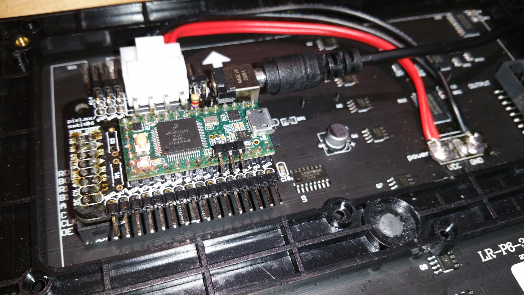
Thanks for the picture, that helps. You have V3, I can tell by the URL on the front, and if you flipped it over you’d see a “V3” marking. This version has the level shifters, so it’s not a 3.3V-5V compatibility issue.
I did have some lights with a 5V 3A power supply but the program would crash and restart
What do you mean by “some lights”, was it displaying the feature demo correctly? Did you see shapes and scrolling text?
At what point in the sketch did it crash?
Does it work again if you go back to the 3A supply?
Just remembered it was actually a 5V 2A supply. Unfortunately I borrowed it from someone at a meetup so I don’t have it available to test. Some of the lights on the panel lit up but I couldn’t really make out any sort of pattern. It looked like rows were trying to illuminate but then the program appeared to crash after a couple of seconds. I’m not sure if it just didn’t have enough power available to drive the LEDs or if there is a fault with the panel. It seemed a bit too random for lack of power
I agree, that doesn’t sound like a power issue. A 5V 2A power supply should be fine for displaying most parts of FeatureDemo , but could fail at the point where it turns all the LEDs bright white.
Let’s try something else, can you try this test program?
https://forums.adafruit.com/viewtopic.php?f=47&t=61007#p317370
I get the blinking LED but again nothing on the display. 
It’s possible you have a cold solder joint somewhere, so there’s no electrical connection between the Teensy and the level shifting chip, or the chip and the panel. You can try looking for a solder joint that doesn’t look quite right, or just use an iron to reheat the pins. Focus on the OE pin, CLK and Latch, any of which could keep the display from showing any pixels.
I’ve tried reflowing those pins as well as any that looked like they could have caused an issue. They all look fine to me though. It doesn’t seem to have solved the problem. The ground pins all are connected fine as I can test the continuity but I can’t seem to do so for the other pins though haven’t really had time to check every combination properly. Shouldn’t I be able to find continuity between a pin on the teensy and the output connector? There are a lot of joints there so its possible some of those aren’t very good. I’m not the best solderer in the world and didn’t really take my time doing it. Do you have info on which pins are connected to the output pins so I can test for bad joints?
The schematic is included in the library, but it’s a bit hard to find. Here’s a link to the PDF version:
https://github.com/pixelmatix/SmartMatrix/blob/master/extras/hardware/SmartMatrixSD_V3.pdf
All the signals going to the panel connector go through buffers, so you can’t do a continuity test. The best I can think of testing with a multimeter is to test the panel pins to see if they are alternating and showing a changing voltage or stuck at 0V or 5V. I’m not sure how well it would work with your particular multimeter. Using a scope would be better if it’s available.
Latch might be a hard signal to see, it’s usually at 0V, with very short pulses high. Make sure the brightness is set to 50% (128) so the OE signal with cycle evenly between 0 and 5.
One more thing you could check: see if there’s any shorts between ground and the panel signals, or the corresponding pins on the Teensy and ground.
I’m running the HEX file you suggested. There are no shorts to ground as far as I can see. Here are the results I got for each pin with estimated timings but not detecting small changes. Looks like there may be an issue with the first blue pin but that shouldn’t cause the entire display to fail. I’ll post an update when I figure out how the minmax/range features on this multimeter work so I can check the pins aren’t stuck.
R1 - 0-5v every 0.5s
G1 - 0-5v every 0.5s
B1 - 0v
R2 - 0-5v every 1s
G2 - 0-5v every 1s
B2 - 0-5v every 1s
A0 - 2.5v
A1 - 2.5v
A2 - 2.5v
A3 - 2.5v
CK - 5v ish
LT - 0v
OE - 2.5v
EDIT: If I’m using it correctly, the latch pin is sat at 0Hz (nothing at all indicating a pulse), the clock at 1733Hz and output enable at 5200Hz. Multimeter might not have enough resolution to see the latch pulse though.
Try modifying the blink sketch (the simple Arduino blink sketch, not a SmartMatrix example), to alternate the Latch pin slowly so you can see it with your meter. Please try it twice, Latch goes to two pins on the Teensy: 8 and 3. Probe the LAT signal at the panel connector, as well as 8 and 3 directly for both tests. Let’s see if we can narrow this down to a fault.
You might want to do the same for CLK (Teensy pin 14), as that is hovering around 5V, though it sounds like you are seeing some movement on CLK.
Using blink with pin 8 on its own and 3 on its own the voltage on the latch pin switches between 0 and 4.42 with the teensy pin voltage switching between 0 and 3.2. Same for the clock pin.
Hmm, we’re running out of things to test. The panel could be a problem. Do you have something else you could use to test the panel, like wiring up an Arduino and using the Adafruit RGB Matrix panel library, or access to another panel to test? You don’t need to wire up all the signals with the Arduino, OE, CLK, LAT, and one of the RGB pins should be sufficient to see if it lights up the panel.
Another option: manually clock in some signals using jumper wires: ground OE, set one or more colors high, and toggle CLK between GND and 5V to shift in some pixels, toggle latch and some LEDs should turn on.
Sorry this isn’t going smoother…
I’ll try it with an uno when I’ve got a bit of free time. Knowing me I’ve probably done something stupid and fried the panel or something… I’m just glad to have someone that can offer a bit more direction with debugging it and its always good to get experience with solving problems. 
Right. Done both of those methods with no success. 
Bummer, seems like the problem is with the panel. Can you post a clear picture of the back of the panel with no Shield in the way?
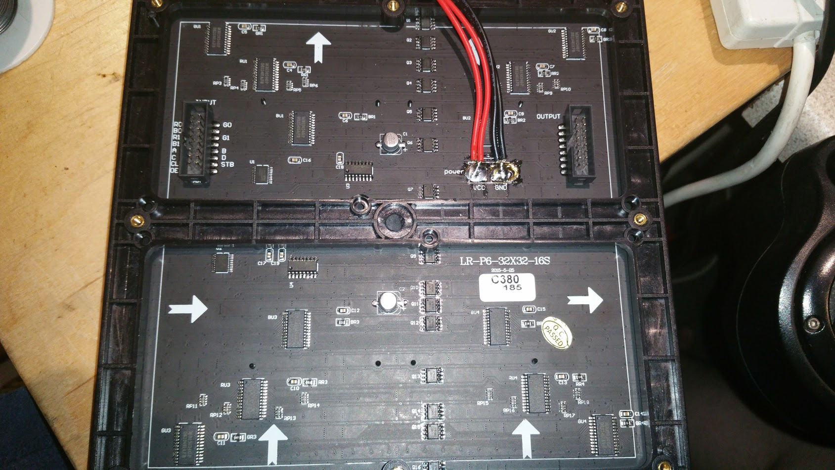
No clear indication of any damage to components and none of the LEDs have signature black mark of death on them so not sure what the issue would be.
At this point, I’d replace the panel…
Ok. Thanks for your help. I’ve contacted the supplier so hopefully we can work out a replacement. I’ll update when I receive the new panel which will hopefully just work.
1 Like