I would like to connect a 8x16 LED module in a arduino the connecting pins begins: RGB, CLK, GND, LAT, GND, OE, GND, R, G, B.
I’m not sure how this panel works from the pinout you described. RGB is listed twice, are there two RGB inputs in parallel like other panels? There are no address pins in the pinout you described, does this panel light up all rows at once? You’ll probably have to do some experimentation to learn more about how the panel works. It doesn’t seem like it will work with SmartMatrix without modification.
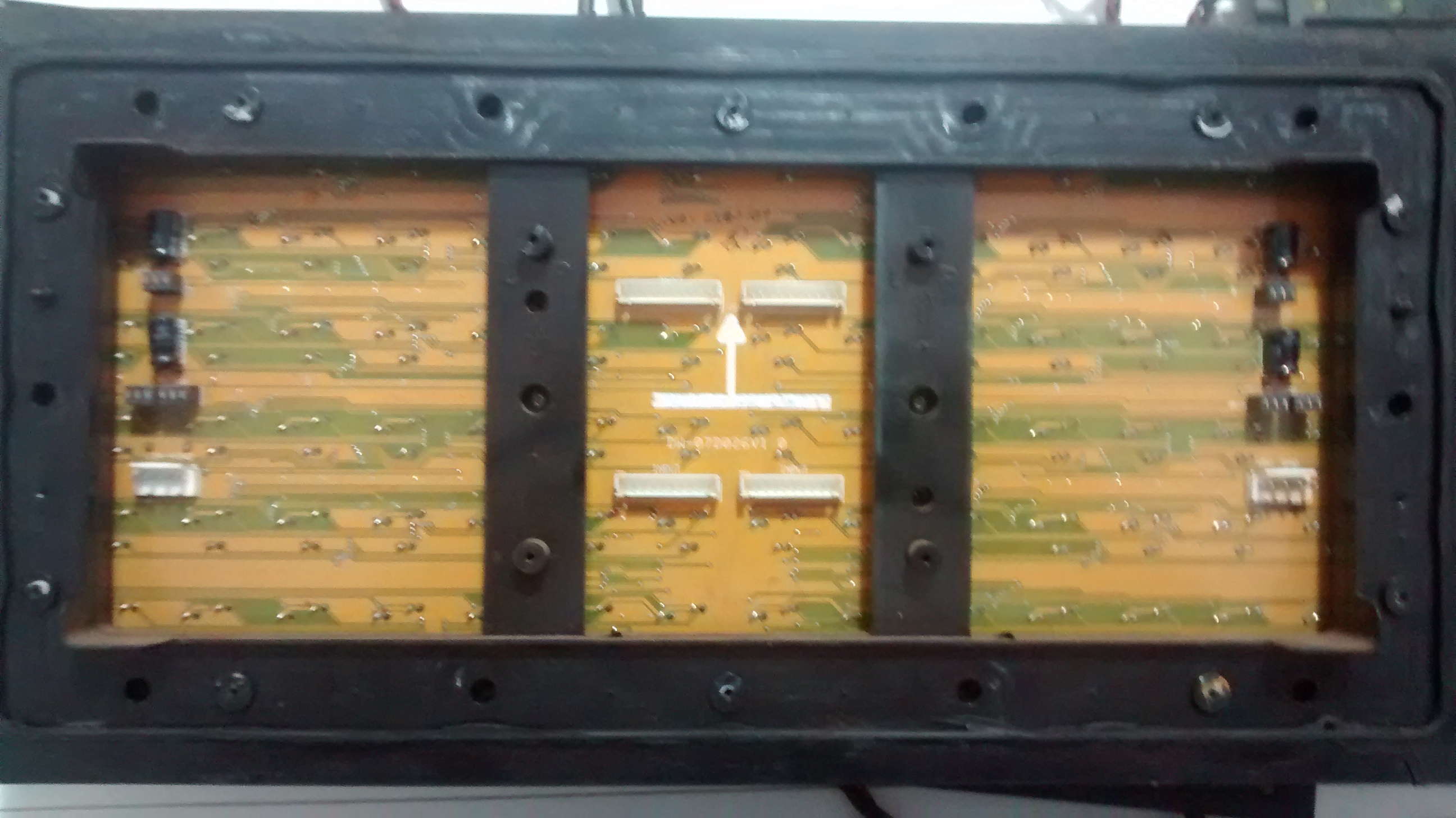
it’s true, I’m sorry I have written wrong, begins with: GND, CKL, GND, LAT, GND, OE, GND, R, G, B. The little knowledge I have is that this panel is divided into two 8x8 module, the connectors showing in the picture, has two that is written INPUT and the other 2 NEXT when do the NEXT patching to INPUT, the panel is 8x16. I hope it has improved my explanation, already grateful for the attention.
Interesting. I think the SmartMatrix Library could be adapted to work with this panel but probably not very easily right now. You could try connecting up a Teensy (either directly or using a SmartMatrix Shield) to the panel and driving it as a 16x32 panel, only using the first set of RGB channels, and see if you can get anything to display on the panel. You could come up with your own mapping functions to convert X,Y coordinates to make them display correctly on the panel. In the future, I’d like to make a user-configurable mapping function so the SmartMatrix Library is able to be used with unusual panels like this one.
Is that in fact I started a little time to mess with these modules, so I have no idea how to do this, if you can help me I will be very grateful.
Sorry, it’s not possible to make these panels work without a lot of work. Keep an eye out for version 4.0 of the library, which may have a feature to make mapping to unique panels like this easier. I may release that version sometime this year, maybe next year.